
A water-based waste drilling fluid electrochemical adsorption treatment device and its process

A waste drilling fluid and adsorption treatment technology, applied in mining wastewater treatment, water/sewage treatment, water/sewage treatment equipment, etc., can solve problems such as high environmental risk, low resource utilization rate, hidden dangers of soil and groundwater pollution, etc., to achieve Save drilling costs, improve recycling performance, and save the effect of harmless treatment

Active Publication Date: 2020-09-08
BC P INC CHINA NAT PETROLEUM CORP +1
View PDF5 Cites 0 Cited by
  • Summary
  • Abstract
  • Description
  • Claims
  • Application Information

AI Technical Summary

Problems solved by technology

[0002] During oil and gas exploration and development drilling operations, a large amount of water-based drilling waste (waste drilling fluid, drilling cuttings) will be produced. The existing water-based drilling waste treatment method is mainly buried after solidification. Disposal by burial and natural evaporation, a small amount of reuse, low resource utilization rate (about 1.5%), and high environmental risk
The existing disposal method is simple. If it is not disposed of properly, it will easily cause hidden dangers of soil and groundwater pollution, and there is a legal risk of being recognized by the government environmental protection department as using the "seepage pit and injection" method to dispose of pollutants.
With the implementation of the new environmental protection law, the traditional solidification landfill treatment method will be strictly prohibited step by step

Method used


Image

  • A water-based waste drilling fluid electrochemical adsorption treatment device and its process
  • A water-based waste drilling fluid electrochemical adsorption treatment device and its process
  • A water-based waste drilling fluid electrochemical adsorption treatment device and its process

Examples


Embodiment 1

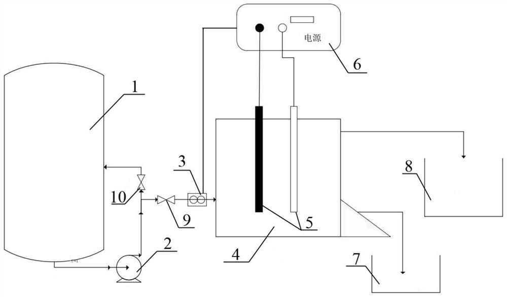
[0036] This embodiment provides a water-based waste drilling fluid electrochemical adsorption treatment device, such as figure 1 As mentioned above, the water-based waste drilling fluid electrochemical adsorption treatment device includes a mud tank 1, a mud pump 2, a flow meter 3, an electrolytic tank 4, an electrode 5, an automatic control system 6, a sludge tank 7, a mud tank 8, and a valve 9 and valve 10;

[0037] The mud tank 1 is in communication with the mud pump 2 and is provided with a valve 10 on the connected pipeline; the mud pump 2 is connected with the flow meter 3 and is provided with a valve 9 on the connected pipeline; the mud tank 1 It communicates with the flow meter 3, and the valve 10 and the valve 9 are sequentially arranged on the connected pipeline; the flow meter 3 communicates with the electrolytic cell 4; the electrode 5 includes an anode and a negative electrode, and the electrode 5 is placed in the electrolytic cell 4 The automatic control system ...

Embodiment 2

[0040]This embodiment provides a water-based waste drilling fluid electrochemical adsorption treatment process, which is carried out by using the water-based waste drilling fluid electrochemical adsorption treatment device provided in Example 1, including the following steps:

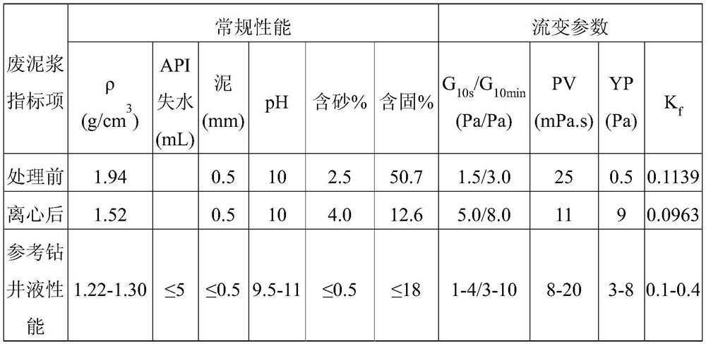
[0041] Utilize the mud pump 2 to pump the drilling fluid after centrifugal treatment (see Table 1 for its parameters) from the mud tank 1 into the electrolytic cell, and adjust the flow rate of the drilling fluid through the automatic control system 6 to adjust the flow meter 3 to be 20L / h. When the drilling fluid flow rate is greater than 20 L / h, the valve 10 is opened, and part of the drilling fluid flows back into the mud tank 1 .

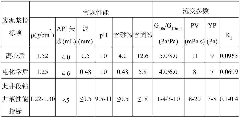
[0042] Then, the electrode is controlled by the automatic control system to carry out electrochemical adsorption, the voltage is adjusted to 10V, and the output current is 2A. The scraper is controlled by the automatic control system to scrape off the solid particles depos...

Embodiment 3

[0048] This embodiment provides a water-based waste drilling fluid electrochemical adsorption treatment process, which is carried out by using the water-based waste drilling fluid electrochemical adsorption treatment device provided in Example 1, including the following steps:

[0049] Utilize the mud pump 2 to pump the drilling fluid after centrifugal treatment (see Table 1 for its parameters) from the mud tank 1 into the electrolytic cell, and adjust the flow rate of the drilling fluid through the automatic control system 6 to adjust the flow meter 3 to be 20L / h. When the drilling fluid flow rate is greater than 20 L / h, the valve 10 is opened, and part of the drilling fluid flows back into the mud tank 1 .

[0050] Then, the electrode is controlled by the automatic control system for electrochemical adsorption, the voltage is adjusted to 15V, and the output current is 4A. The scraper is controlled by the automatic control system to scrape off the solid particles deposited on ...


PUM


Abstract

The invention provides an electrochemical adsorption treatment device and process for water-based waste drilling fluid. The electrochemical adsorption treatment device for the water-based waste drilling fluid comprises a mud tank, a mud pump, a flow meter, an electrolytic bath, an electrode and an automatic control system, wherein the mud tank is circularly communicated with the mud pump; the mud pump is communicated with the flow meter; the mud tank is communicated with the flow meter; the flow meter is communicated with the electrolytic bath; the electrode comprise an anode and a cathode; the electrode is arranged in the electrolytic bath; the automatic control system is electrically connected with the electrode; the automatic control system is electrically connected with the flow meter. According to the electrochemical adsorption treatment device and process for the water-based waste drilling fluid, which are provided by the invention, a chemical treating agent is not added; an effective component in drilling fluid is not destroyed; inferior solid phases of a superfine micro-particle and the like in waste drilling fluid can be effectively removed; thus, main performance indexes of the density, the silt content, the solid content and the like of the waste drilling fluid are decreased; the rheological characteristic of the waste drilling fluid is improved, and the recycling performance index requirement of waste-based drilling fluid is met.

Description

technical field [0001] The invention belongs to the technical field of oil and gas field drilling in the petroleum industry, and relates to a water-based waste drilling fluid electrochemical adsorption treatment device and a process thereof. Background technique [0002] During oil and gas exploration and development drilling operations, a large amount of water-based drilling waste (waste drilling fluid, drilling cuttings) will be produced. The existing water-based drilling waste treatment method is mainly buried after solidification. Disposal by burial and natural evaporation, a small amount of reuse, low resource utilization rate (about 1.5%), and high environmental risk. The existing disposal method is simple. If it is not disposed of properly, it will easily cause hidden dangers of soil and groundwater pollution, and there is a legal risk of being recognized by the government environmental protection department as using the "seepage pit and injection" method to dispose o...

Claims


Application Information

Patent Timeline
Patent Type & Authority Patents(China)
IPC IPC(8): C02F1/469C02F1/461C02F103/10
CPCC02F1/4672C02F1/4691C02F2103/10C02F2201/46105C02F2201/46135C02F2201/4614C02F2201/4615C02F2201/4618
Inventor 任雯谢水祥孙静文仝坤许毓张明栋刘晓辉李树森
Owner BC P INC CHINA NAT PETROLEUM CORP
Learn More