Spinning machine comprising a plurality of workplaces and a suction appliance

A technology of spinning machine and air-jet spinning machine, applied in the field of spinning machine

Active Publication Date: 2017-12-08
RIETER INGOLSTADT GMBH
View PDF5 Cites 3 Cited by
  • Summary
  • Abstract
  • Description
  • Claims
  • Application Information

AI Technical Summary

Problems solved by technology

But in today's spinning machines equipped with an increasing number of spinning positions, this mechanical design encounters its limitations

Method used


Image

  • Spinning machine comprising a plurality of workplaces and a suction appliance
  • Spinning machine comprising a plurality of workplaces and a suction appliance
  • Spinning machine comprising a plurality of workplaces and a suction appliance

Examples


Embodiment Construction

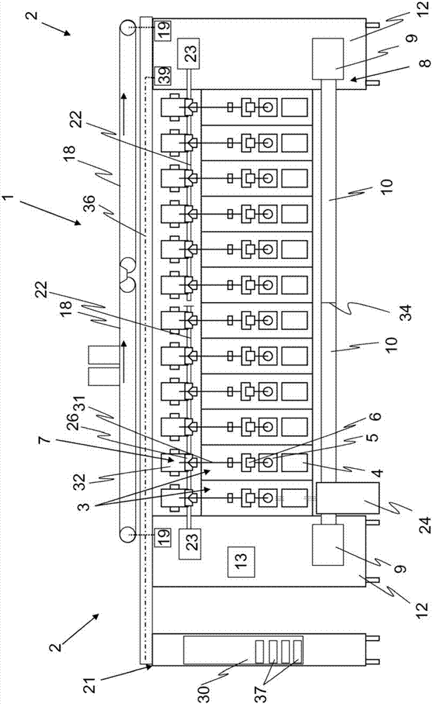
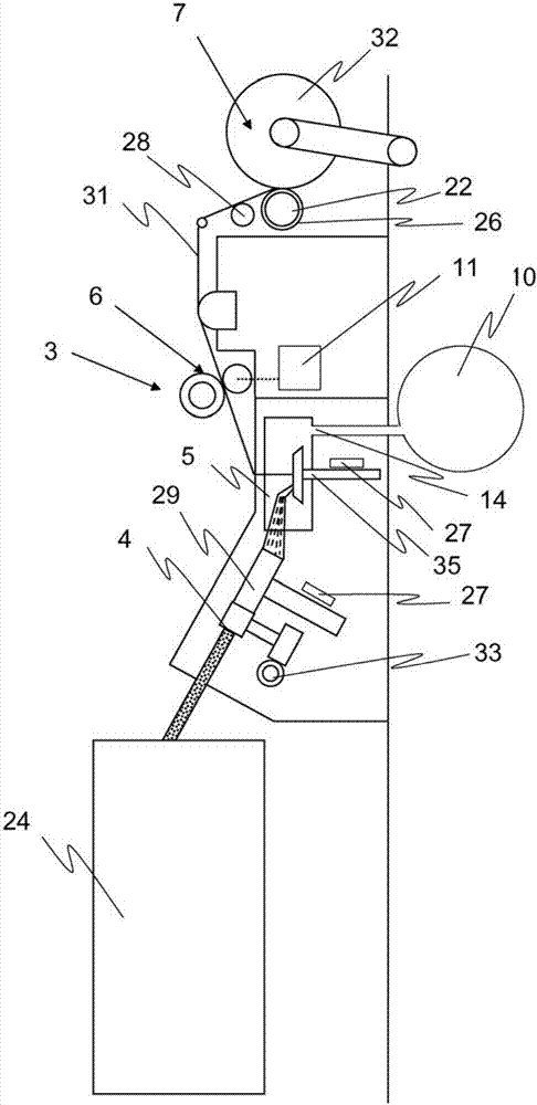
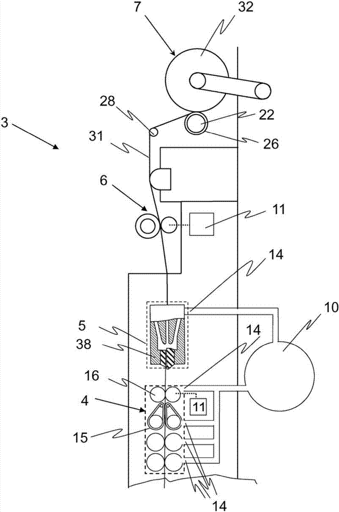
[0039] figure 1 A schematic illustration of a spinning machine 1 is shown, which is suitable in a special manner for arranging a plurality of work stations 3 side by side in the longitudinal direction of the spinning machine 1 . The workstations 3 are arranged side by side between the two front ends 2 and each have a known number of working means 4 , 5 , 6 , 7 for producing and winding the yarn 31 . Each station 3 has a conveying device 4 by means of which the fibrous material from the container 24 is conveyed to the spinning chamber 5 in which the fibrous material is spun into a yarn 31 . The yarn 31 is drawn out of the spinning chamber 5 by means of the yarn delivery device 6 and finally wound onto the bobbin 32 by means of the winding device 7 . Furthermore, the spinning machine 1 has a suction device 8 for supplying the station 3 with a low pressure and also for removing pollutants and waste from the station 3 when the yarn is attached and when the station 3 is maintained...


PUM


Abstract

A spinning machine (1) features a multiple number of work stations (3) arranged side by side between two front-side ends (2) of the spinning machine (1) on at least one longitudinal side of the spinning machine (1), each of which features a multiple number of work elements for the production and winding of a yarn (31), whereas the work elements comprise at least one feed device (4), one spinning chamber (5), one draw-off device (6) and one winding device (7). The spinning machine (1) features drives for driving the work elements and a suction device (8) for generating negative pressure at the work stations (3). The suction device (8) includes at least one negative pressure source (9) and at least two negative pressure channels (10), which extends in the longitudinal direction of the spinning machine (1) only over one part of the work stations (3). Thereby, each work station (3) features an individual drive (11), in particular an individual electrical drive (11), for the draw-off device (6).

Description

technical field [0001] The invention relates to a spinning machine with a plurality of stations arranged side by side in the longitudinal direction of the spinning machine on at least one longitudinal side between two end-side ends of the spinning machine, the stations each having a plurality of A working mechanism is used to manufacture and wind the yarn, wherein the working mechanism includes at least one conveying device, a spinning chamber, a yarn drawing device and a winding device; a driving device for driving the working mechanism; A suction device that generates low pressure. Background technique [0002] In the state of the art for a long time all working mechanisms of the workstations were generally driven collectively in spinning machines, so that the machine can be operated economically. For this purpose, correspondingly identical working mechanisms are driven by a central drive arranged at the end of the spinning machine, which drives the working mechanisms of ...

Claims


Application Information

Patent Timeline
Patent Type & Authority Applications(China)
IPC IPC(8): D01H4/08D01H1/02B65H54/28
CPCB65H54/28D01H1/02D01H4/08D01H1/20D01H4/24D01H11/00D01H1/115D01H1/11D01H4/02D01H7/00
Inventor R·波赫A·斯蒂芬
Owner RIETER INGOLSTADT GMBH
Why Eureka
Try Eureka