Knife-shaped gate valve body and manufacturing process thereof

A technology of knife gate valve and valve body, which is applied in the directions of casting mold, core, sliding valve, etc., can solve the problems of poor sealing performance, reduced sealing effect, and reduced sealing effect.

Inactive Publication Date: 2017-12-08
江苏盐发机械有限公司
View PDF0 Cites 2 Cited by
  • Summary
  • Abstract
  • Description
  • Claims
  • Application Information

AI Technical Summary

Problems solved by technology

[0003] However, in the existing knife-type gate valve, due to the limitation of machining accuracy, the distance between the top block and the valve wall on the opposite side cannot be exactly equal to the thickness of the valve plate, and in order to facilitate the insertion of the valve plate, the top block and the opposite side The distance between the valve wall on the side is usually slightly larger than the thickness of the valve plate. Only in this way can the valve plate be inserted or withdrawn smoothly (that is, the valve can be opened or closed smoothly); however, the distance between the top block and the valve wall on the opposite side If the spacing is slightly greater than the thickness of the valve plate, it will reduce the sealing effect when the valve is closed; With the increase of time, due to the opening and closing of the valve, there will be a gap between the top block and the valve plate due to wear, which will reduce the sealing effect; it can be seen that the knife-type gate valve with this valve body has poor sealing performance

Method used


Image

  • Knife-shaped gate valve body and manufacturing process thereof
  • Knife-shaped gate valve body and manufacturing process thereof
  • Knife-shaped gate valve body and manufacturing process thereof

Examples


Embodiment 1

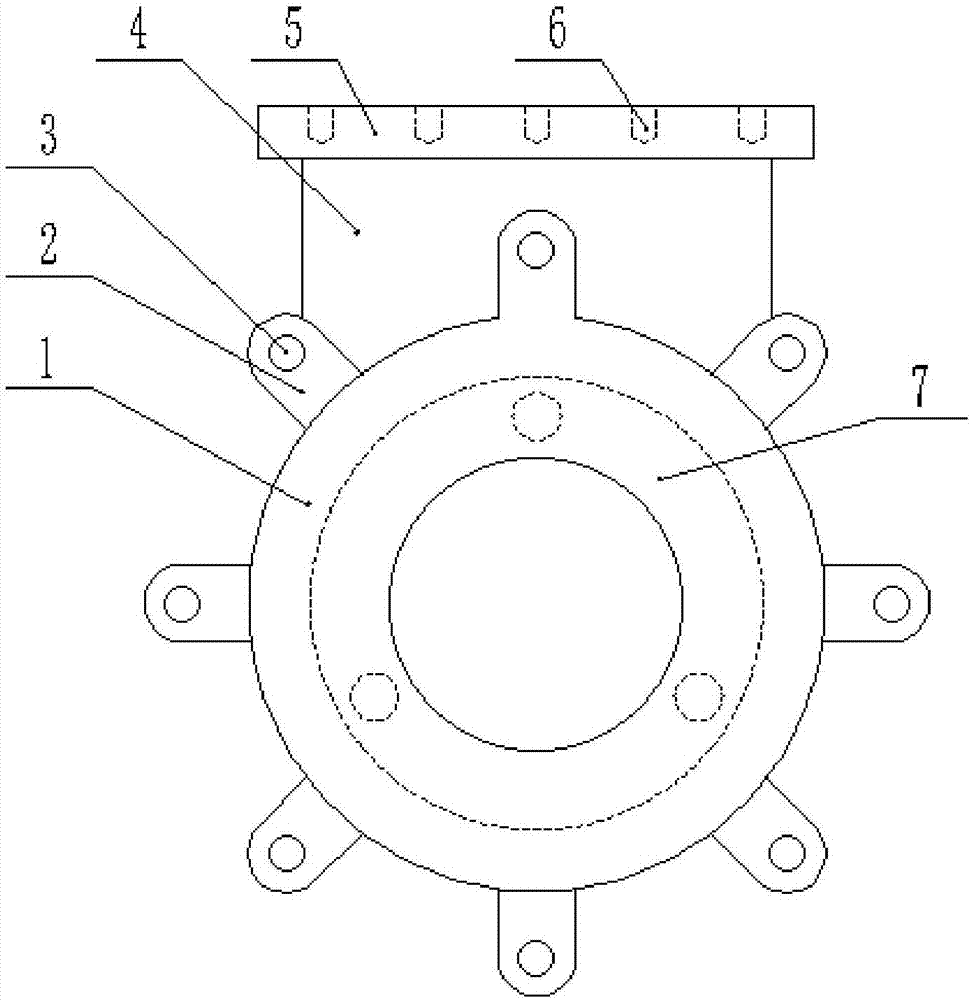
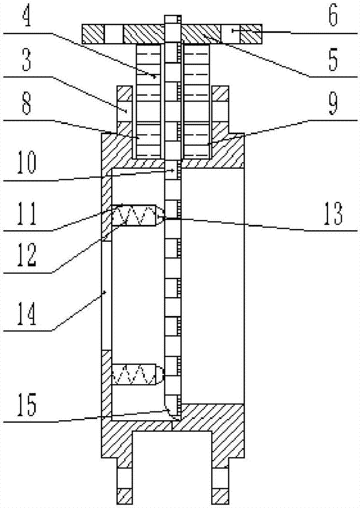
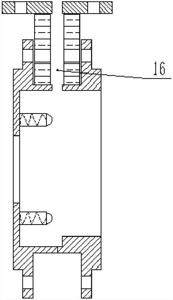
[0063] Combine below Figure 1-3 The structure of the knife-type gate valve body of this embodiment is described in detail: a knife-type gate valve body includes a casing 1, and the casing 1 is bonded by a left valve body 8 and a right valve body 9 with an annular hollow structure and the same outer diameter. Splicing structure, so as to form the cavity structure inside the shell 1, the same number of connecting blocks 2 are arranged at equal intervals along the respective circumferential directions on the sides of the left valve body 8 and the right valve body 9 And the positions are one-to-one correspondence, the connecting block 2 is welded and fixed, and the two connecting blocks 2 on the left valve body 8 and the right valve body 9 at the same corresponding position form a groove structure, and each connecting block 2 has a mounting hole 3 inside ;

[0064] The opening of the left valve body 8 away from the right valve body 9 side is used as the water inlet 14, and the e...

Embodiment 2

[0077] Combine below Figure 1-3 The structure of the knife-type gate valve body of this embodiment is described in detail: a knife-type gate valve body includes a casing 1, and the casing 1 is bonded by a left valve body 8 and a right valve body 9 with an annular hollow structure and the same outer diameter. Splicing structure, so as to form the cavity structure inside the shell 1, the same number of connecting blocks 2 are arranged at equal intervals along the respective circumferential directions on the sides of the left valve body 8 and the right valve body 9 And the positions are one-to-one correspondence, the connecting block 2 is welded and fixed, and the two connecting blocks 2 on the left valve body 8 and the right valve body 9 at the same corresponding position form a groove structure, and each connecting block 2 has a mounting hole 3 inside ;

[0078] The opening of the left valve body 8 away from the right valve body 9 side is used as the water inlet 14, and the e...

Embodiment 3

[0091] This embodiment provides a production process for a knife-type gate valve body, and the specific operation steps are as follows:

[0092] (1) Smelting raw materials:

[0093] a. Add the raw material of the knife-type gate valve body into the furnace, raise the temperature in the furnace to 1550°C, and the raw material is smelted to form an alloy solution;

[0094] b. Cool the alloy solution obtained in the previous step. When cooling, combine water cooling and air cooling. First use water cooling to cool the alloy solution to 455°C at a cooling rate of 26°C / s to form an alloy, then air cool to 355°C, and then use water cooling Water-cool the alloy to room temperature at a cooling rate of 12°C / s;

[0095] c. Heating, put the alloy cooled in the previous step into the furnace for secondary melting, raise the temperature in the furnace to 1830°C, and the alloy is secondary smelted to form an alloy solution;

[0096] d. Hot ladle, pour the alloy solution in the furnace in...


PUM

PropertyMeasurementUnit
thicknessaaaaaaaaaa
thicknessaaaaaaaaaa

Abstract

The invention discloses a knife-type gate valve body, which includes a shell, which is composed of a left valve body and a right valve body with an annular hollow structure and the same outer diameter, which are bonded and spliced, thereby forming a cavity structure inside the shell. The left valve body is far away from the The opening on one side of the right valve body is used as a water inlet, and a ring-shaped boss extends outward from the edge of the water inlet. A telescopic sleeve is fixed inside the ring-shaped boss along a direction perpendicular to the water inlet, and a spring is fixed inside the telescopic sleeve. One end is fixed on the ring-shaped boss, and the other end is fixed with the top block at the top of the telescopic sleeve. The corresponding positions of the fixed block, the connecting plate and the shell are provided with a through chute along the vertical centerline of the shell, thereby forming a slideway. It also includes a valve plate slidingly matched with the slideway, so as to extend into the inside of the shell through the slideway; the present invention realizes the elimination of the gap when the knife-type gate valve body is closed through the cooperation of the valve plate, the telescopic head, the spring and the top block. The sealing degree of the knife gate valve is guaranteed, and the use efficiency of the knife gate valve is improved.

Description

technical field [0001] The invention belongs to the technical field of valves, and in particular relates to a knife-type gate valve body and a production process thereof. Background technique [0002] At present, the knife-type gate valve body in the pipeline used to transport viscous liquids in papermaking, sewage treatment and other industries is a traditional valve body. The knife-type gate valve has simple and compact structure, reasonable design, light weight and material saving, reliable sealing, It has the advantages of light and flexible operation, small size, smooth passage, small flow resistance, light weight, easy installation and disassembly, etc. It can work normally under the working pressure of 1.0MPa-2.5MPa and operating temperature of -29-650℃; knife gate valve Its gate has a shearing function, which can scrape off the sticky matter on the sealing surface and automatically remove debris, and the stainless steel gate can prevent seal leakage caused by corrosi...

Claims


Application Information

Patent Timeline
Patent Type & Authority Applications(China)
IPC IPC(8): F16K27/04F16K3/30B29C69/00C08L63/00C08L71/12C08K13/02C08K3/34C08K3/04C08K5/17B22C9/04
CPCF16K27/04B22C9/04B29C69/00C08L63/00F16K3/30
Inventor 黄军龙
Owner 江苏盐发机械有限公司
Why Eureka
Try Eureka