Reasonably-structured special power vaporizer for high-efficiency methanol burner

A vaporizer and burner technology, which is applied in the field of high-efficiency methanol burner special power vaporizers, can solve problems such as a large amount of exhaust gas and pollute the environment, and achieve the effects of low production cost, long service life and easy realization.

Pending Publication Date: 2017-12-08
中润海精密科技有限公司
View PDF3 Cites 0 Cited by
  • Summary
  • Abstract
  • Description
  • Claims
  • Application Information

AI Technical Summary

Problems solved by technology

[0003] At present, traditional burners use diesel oil, heavy oil, gas, etc. as fuel. Diesel, heavy oil, and gas are...

Method used


Image

  • Reasonably-structured special power vaporizer for high-efficiency methanol burner
  • Reasonably-structured special power vaporizer for high-efficiency methanol burner
  • Reasonably-structured special power vaporizer for high-efficiency methanol burner

Examples


Embodiment 1

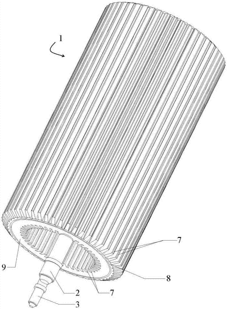
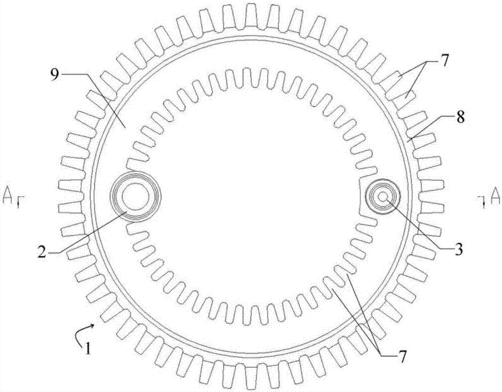
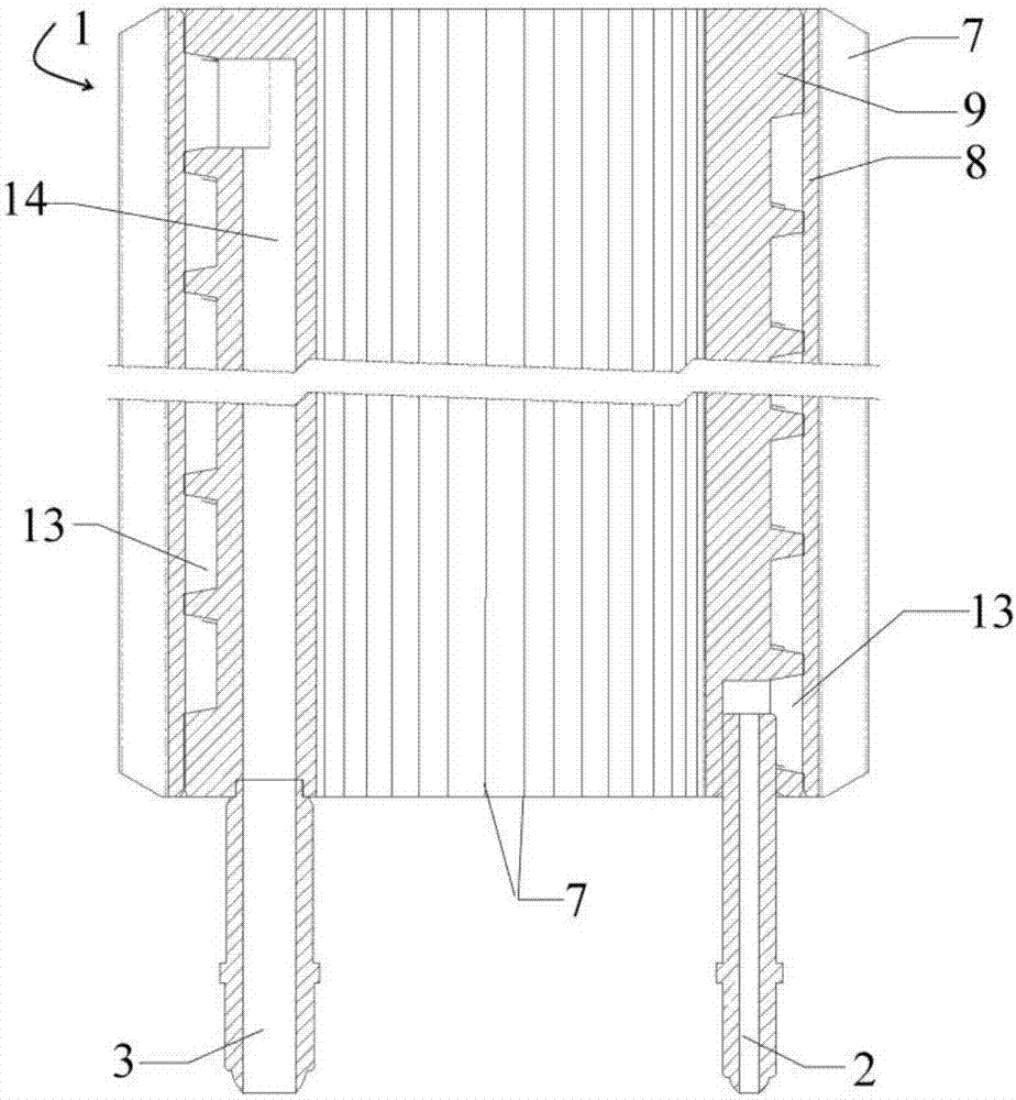
[0032] Such as Figure 1-2 The shown power carburetor with reasonable structure and dedicated to high-efficiency methanol burners includes a power carburetor body 1, and the bottom of the power carburetor body 1 is respectively provided with a methanol liquid inlet 2 and a methanol vaporization outlet 3. The power carburetor body 1 includes a carburetor outer casing 8 and a carburetor inner casing 9 , wherein the power carburetor body 1 is a hollow cylindrical power carburetor body 1 . In addition, a group of ribs 7 are uniformly provided on the carburetor outer casing 8 and the carburetor inner casing 9 . Moreover, the fins 7 are arranged on the carburetor outer casing 8 and the carburetor inner casing 9 from top to bottom. The carburetor body 1 , methanol liquid inlet 2 , methanol vaporization outlet 3 and fins 7 are made of stainless steel, and a high-temperature-resistant coated sand layer is provided on the outside of the stainless steel material.

[0033] In addition, ...

Embodiment 2

[0035] Such as Figure 1-2The shown power carburetor with reasonable structure and dedicated to high-efficiency methanol burners includes a power carburetor body 1, and the bottom of the power carburetor body 1 is respectively provided with a methanol liquid inlet 2 and a methanol vaporization outlet 3. The power carburetor body 1 includes a carburetor outer casing 8 and a carburetor inner casing 9 , wherein the power carburetor body 1 is a hollow cylindrical power carburetor body 1 . In addition, a group of ribs 7 are uniformly provided on the carburetor outer casing 8 and the carburetor inner casing 9 . Moreover, the fins 7 are arranged on the carburetor outer casing 8 and the carburetor inner casing 9 from top to bottom. The carburetor body 1 , methanol liquid inlet 2 , methanol vaporization outlet 3 and fins 7 are made of stainless steel, and a high-temperature-resistant coated sand layer is provided on the outside of the stainless steel material.

[0036] In addition, i...


PUM


Abstract

The invention discloses a reasonably-structured special power vaporizer for a high-efficiency methanol burner. The special power vaporizer comprises a power vaporizer body. The bottom of the power vaporizer body is provided with a methanol inlet and a methanol vaporization outlet. The power vaporizer body comprises a vaporization outer sleeve and a vaporization inner sleeve. A spiral channel and an output channel are formed between the vaporization outer sleeve and the vaporization inner sleeve. One end of the spiral channel is connected with the methanol inlet and extends upwards from the bottom of the power vaporizer body. The spiral channel extends to the top of the power vaporizer body along the power vaporizer body and is connected with the output channel. The output channel is connected with the methanol vaporization outlet. The special power vaporizer is simple and reasonable in structure. A fuel inlet is formed in the bottom, and a fuel outlet is formed in the top. The size of the methanol inlet is smaller than that of the output channel and that of the methanol vaporization outlet. The heat exchange area is increased. Besides, the power vaporizer is light in overall weight. The heat storage capacity is greatly increased. The service life of the power vaporizer is greatly prolonged.

Description

technical field [0001] The invention belongs to the technical field of biomass energy, in particular to the technical field of methanol burners, in particular to a special-purpose power vaporizer for high-efficiency methanol burners with reasonable structure. Background technique [0002] A burner is a device that makes fuel and air mixed and ejected in a certain way. Household water heaters, gas stoves, and even lighters are all types of burners. Burners can be divided into oil burners, gas burners, etc. according to the fuel method. [0003] At present, traditional burners use diesel oil, heavy oil, gas, etc. as fuel. Diesel oil, heavy oil, and gas are non-renewable resources, and after combustion, a large amount of exhaust gas will be generated, polluting the environment. However, the commonly used gas fuels mainly include artificial gas, natural gas, and liquefied petroleum gas. In recent years, with the popularization and use of human beings, the above-mentioned gaseo...

Claims


Application Information

Patent Timeline
IPC IPC(8): F23D11/44
CPCF23D11/44
Inventor 李岳申阁张世萍
Owner 中润海精密科技有限公司
Why Eureka
Try Eureka