
Flexible-layout vision-assisted laser galvanometer scanning system and on-site calibration method thereof

An auxiliary laser and galvanometer scanning technology, applied in the direction of optical devices, image data processing, measuring devices, etc., can solve the problems of poor adaptability and low efficiency, and achieve the effect of enhancing adaptability

Active Publication Date: 2017-12-08
NANJING UNIV OF AERONAUTICS & ASTRONAUTICS
View PDF4 Cites 17 Cited by
  • Summary
  • Abstract
  • Description
  • Claims
  • Application Information

AI Technical Summary

Problems solved by technology

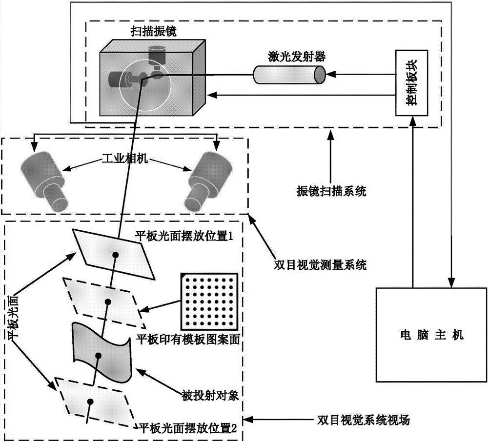
[0004] Aiming at the problems of poor adaptability and low efficiency of the traditional visual aided laser galvanometer scanning system in different field environments, the present invention provides a visually assisted laser galvanometer scanning system with a flexible layout and a field calibration method thereof. The relative position of the visual measurement system and the laser galvanometer scanning system can be adjusted according to different situations in the field application, and the camera lens of the vision system can be replaced according to the distance between the scanned object and the visual measurement system, so as to enhance the system adaptability Effect

Method used


Image

  • Flexible-layout vision-assisted laser galvanometer scanning system and on-site calibration method thereof
  • Flexible-layout vision-assisted laser galvanometer scanning system and on-site calibration method thereof
  • Flexible-layout vision-assisted laser galvanometer scanning system and on-site calibration method thereof

Examples


Embodiment Construction

[0033] The present invention provides a visually assisted laser galvanometer scanning system with a flexible structure layout and its fast on-site calibration method. In order to make the purpose, technical solution and effect of the present invention clearer and clearer, the present invention is further described in detail with reference to the accompanying drawings and examples . It should be pointed out that the specific implementations described here are only used to explain the present invention, not to limit the present invention.

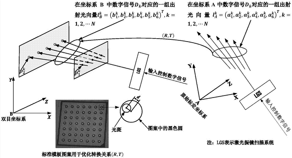
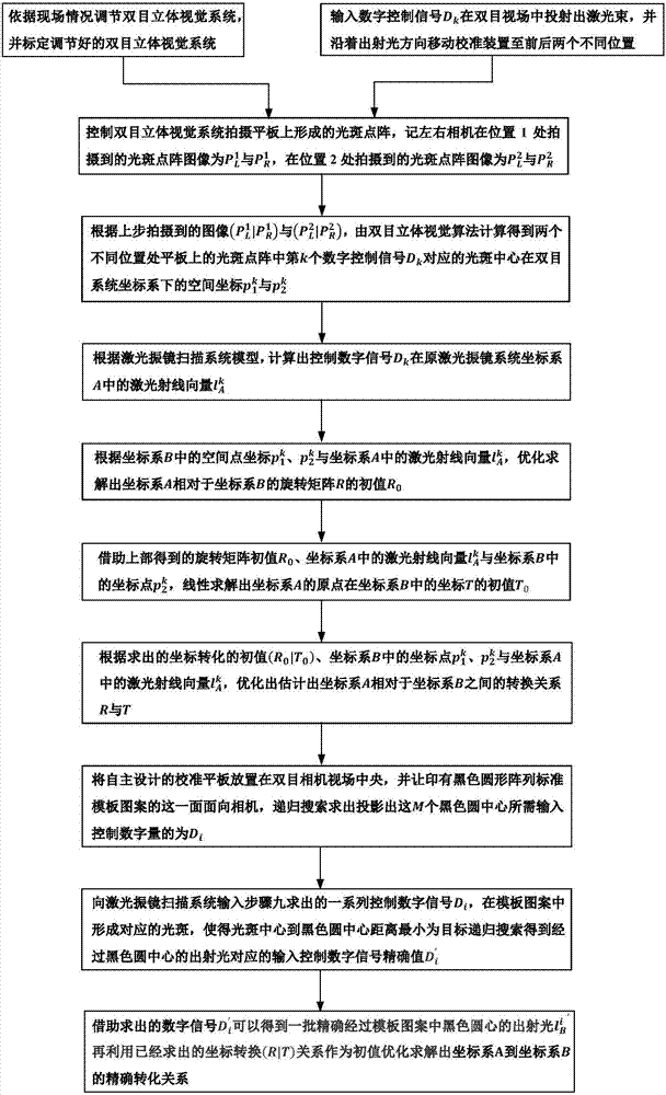
[0034] The quick on-site calibration method of the vision-assisted laser galvanometer scanning system with flexible structure layout proposed by the present invention is to determine the coordinate conversion relationship between the coordinate system where the laser galvanometer scanning system has the calibration results and the coordinate system of the binocular stereo vision system in the field layout. To achieve the purpose of rapid on-s...


PUM


Abstract

The invention provides a flexible-layout vision-assisted laser galvanometer scanning system and an on-site calibration method thereof. The system comprises a laser galvanometer scanning system, a visual positioning device and a calibration device. The calibration device is a piece of calibration flat plate, wherein one surface of the calibration flat plate is an interval-known black circular array standard template pattern, and the other surface is a smooth plane suitable for laser spot imaging. The calibration method enables the calibration result of the laser galvanometer scanning system to be also suitable to a field binocular system coordinate system through coordinate transformation relation of coordinate systems of the calibration results of the binocular stereo vision system coordinate system and an original galvanometer scanning system, thereby realizing on-site calibration of the laser galvanometer scanning system; the calibration method is simple to operate, short in consumed time, high in calibration precision and high in stability; and the calibration method can greatly improve field use flexibility and operability of the vision-assisted laser galvanometer scanning system.

Description

technical field [0001] The invention relates to the field of calibration of vibrating mirror scanning systems, in particular to a visually assisted laser vibrating mirror scanning system with flexible layout and an on-site calibration method thereof. Background technique [0002] With the help of the laser galvanometer scanning system, laser positioning projection and laser three-dimensional measurement can be realized, so it is widely used in the field of aviation manufacturing and aviation manufacturing, such as aircraft parts assembly, composite material layup, pattern spraying, etc. Generally, the laser galvanometer scanning system needs to be calibrated before use, that is, to calibrate the relationship between the deflection of the laser galvanometer scanning system's own scanning head and the azimuth vector of the outgoing laser beam, and to calibrate the relationship between the laser galvanometer scanning system and the scanned object. pose relationship. Combining ...

Claims


Application Information

Patent Timeline
Patent Type & Authority Applications(China)
IPC IPC(8): G01B11/25G06T7/70G06T7/80
CPCG06T7/70G06T7/85G01B11/2518G06T2207/10012
Inventor 涂俊超张丽艳王敏刚
Owner NANJING UNIV OF AERONAUTICS & ASTRONAUTICS
Learn More