
Non-resonance triaxial angular rate sensor for nano-optical grating

An angular rate sensor and rate sensor technology, which is applied in the field of micro-inertial navigation to achieve the effects of high resolution, little influence of external vibration or shock, and simple structure

Pending Publication Date: 2017-12-08
ZHONGBEI UNIV
View PDF11 Cites 7 Cited by
  • Summary
  • Abstract
  • Description
  • Claims
  • Application Information

AI Technical Summary

Problems solved by technology

The principle has been verified in distance measurement and acceleration sensors, but nano gratings have not been used in angular rate sensors

Method used


Image

  • Non-resonance triaxial angular rate sensor for nano-optical grating
  • Non-resonance triaxial angular rate sensor for nano-optical grating
  • Non-resonance triaxial angular rate sensor for nano-optical grating

Examples


Embodiment Construction

[0036] Embodiments of the present invention are described in detail below, examples of which are shown in the drawings, wherein the same or similar reference numerals designate the same or similar elements or elements having the same or similar functions throughout. The embodiments described below by referring to the figures are exemplary only for explaining the present invention and should not be construed as limiting the present invention.

[0037] In the description of the present invention, it should be understood that the orientations or positional relationships indicated by the terms "center", "upper", "lower", "front", "rear", "left", "right" etc. are based on the attached The orientation or positional relationship shown in the figure is only for the convenience of describing the present invention and simplifying the description, and does not indicate or imply that the referred combination or element must have a specific orientation, be constructed and operated in a spec...


PUM


Abstract

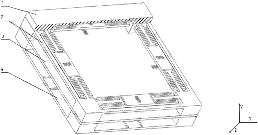
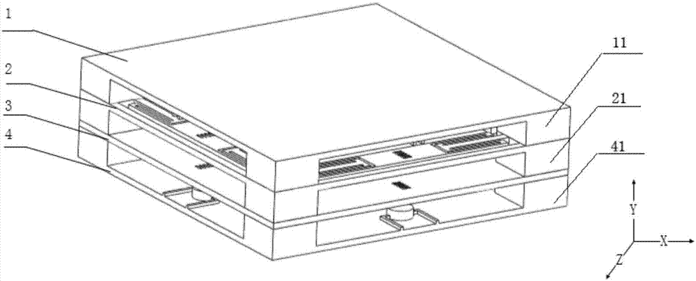
The invention relates to a non-resonance triaxial angular rate sensor for a nano-optical grating. The non-resonance triaxial angular rate sensor mainly structurally comprises an upper base plate, a movable optical grating layer, a fixed optical grating layer, a lower base plate, photoelectric detectors, a detection beam, a linking block, a mass block, a movable optical grating, a boss, laser sources and leads, wherein the four photoelectric detectors and the leads are arranged in the upper base plate, the movable optical grating layer is provided with a support framework, the mass block with the movable optical grating, the detection beam and the linking block, the fixed optical grating layer is provided with four fixed optical gratings, and the four laser sources and the leads are arranged in the lower base plate. The non-resonance triaxial angular rate sensor does not need to be driven and has the advantages of high measuring range, simple structure, small cross coupling error and small external impact or vibration influence.

Description

technical field [0001] The invention belongs to the related field of micro-inertial navigation technology, and in particular relates to a nano-grating non-resonant three-axis angular rate sensor. Background technique [0002] The micro-mechanical electronic angular rate sensor is a high-tech product developed in the 1990s. It is mainly used for attitude measurement of aerospace vehicles. great attention to the field. [0003] At present, an angular rate sensor is generally composed of a driving structure, a sensitive mass, a detection mechanism, and a conversion circuit. Due to the inevitable errors in the production process, the angular rate sensor cannot achieve the symmetry of the original design, and the drive caused by structural errors The coupling of modal energy to the detection mode will directly cause a large output noise, and the error caused by processing is generally compensated by placing the detection module on the meter head and correspondingly compensated b...

Claims


Application Information

Patent Timeline
IPC IPC(8): G01C19/5656G01B11/02
CPCG01B11/02G01C19/5656
Inventor 李孟委梁洲鑫耿浩吴倩楠李秀源
Owner ZHONGBEI UNIV
Learn More