Device capable of compressing divergence angle of VCSEL laser

A technology of laser and divergence angle, applied in the direction of controlling laser output parameters, lasers, laser parts, etc. It can solve the problems of large light-emitting angle, no devices, and products that cannot work normally, so as to increase manufacturability and reduce installation. puzzle effect

Pending Publication Date: 2017-12-08
SHENZHEN 3KM PHOTOELECTRIC SCI & TECH CO LTD
View PDF6 Cites 1 Cited by
  • Summary
  • Abstract
  • Description
  • Claims
  • Application Information

AI Technical Summary

Problems solved by technology

However, when the vcsel laser is used for long-distance illumination, the divergence angle of its spot is relatively large. The divergence angle of the common high-power VCSEL lasers on the market often reaches 20°. In addition, the VCSEL laser needs to reach a certain power and often requires the use of multiple independent lasers. The integration of the light-emitting points of the VCSEL makes the light-emitting area of ​​the VCSEL laser often many times larger than that of other edge-emitting lasers. This is not good for the optical system at the back end of the VCSEL. Therefore, how to compress the beam divergence angle on the existing laser, Improving the overall brightness of the VCSEL laser light has become a very real problem
Some studies have found that when using ordinary lenses to compress the spot of VCSEL laser lamps, it is often impossible to increase the optical etendue of the laser, and it is not helpful to improve the overall brightness of the VCSEL laser. Therefore, how to compress the spot without changing the area of ​​​​the light source? The divergence angle of the exit spot of the VCSEL laser has become a difficult problem to be solved
[0003] Someone uses a microlens array on the market to compress a single luminous point of a VCSEL laser, such as figure 2 As shown, the microlens array 20a uses the non-light-emitting area between the light-emitting points 11a of the VCSEL laser 10a to perform spot compression, as shown in figure 2 As shown, each lens unit 21a in the microlens array 20a utilizes the non-light-emitting surface between the light-emitting points 11a of the VCSEL laser 10a, adopts a positive lens array, and compresses the angle of the outgoing beam of the laser. At the same time, each light-emitting After point imaging, the image of a single luminous point also becomes larger, but the enlarged area will not exceed the non-luminous area between the luminous point and the luminous point of the VCSEL laser, so that the output spot of the VCSEL laser can be compressed without changing the area of ​​the light source divergence angle; yet, in the process of implementing the above-mentioned method, it is found that there is a big problem, the main problem is because the distance between the light-emitting points 11a of the VCSEL laser 10a is too small, often only tens of microns, while the light-emitting The angle is relatively large, and the light beams between the adjacent light-emitting points 11a of the VCSEL laser 10a will converge within a very short distance. If the microlens array 20a is used outside this distance, the original effect will be lost, so the conventional layout The microlens array 20a used in the VCSEL laser 10a faces two extreme problems
1. In order to increase the processing thickness of the microlens array 20a (avoiding it from being too thin to affect the strength), the microlens must be as close as possible to the device. In the microlens array 20 used by the VCSEL laser 10a of the conventional layout, the microlens array 20 In order to achieve a thickness of 0.2 to 0.3mm, the surface of the microlens array 20 needs to be close to the surface of the VCSEL laser 10a by about 0.05mm. As we all know, the VCSEL laser 10a is a formal chip, and the surface needs a wire bonding process, so this method is very likely to cause microlenses. The contact between the array and the surface of the laser or the gold wire will seriously cause the product to fail to work normally; 2. Even if the distance between the microlens and the light-emitting surface of the VCSEL laser 10a is 0.05mm, the microlens array 20a of 0.2-0.3mm is in the actual It is also very difficult to do in processing
The above two reasons have caused the current situation. Although everyone knows that the microlens array can compress the beam angle of the VCSEL laser and improve the brightness of the device, there is no relevant actual device in the current market.

Method used


Image

  • Device capable of compressing divergence angle of VCSEL laser
  • Device capable of compressing divergence angle of VCSEL laser

Examples


Embodiment Construction

[0012] The present invention will be described in further detail below in conjunction with the embodiments and with reference to the accompanying drawings.

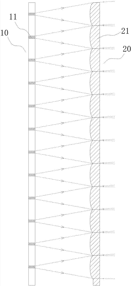
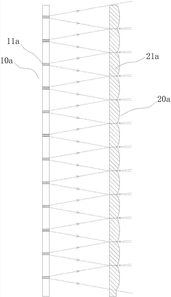
[0013] For a device capable of compressing the divergence angle of a VCSEL laser in this embodiment, please refer to the attached figure 1 , comprising a VCSEL laser 10 arranged at one end, the light-emitting surface of the VCSEL laser 10 is provided with a microlens array 20 at intervals, each microlens of the microlens array 20 is a plano-convex lens 21, and the convex surface of the plano-convex lens 21 Close to and towards the light-emitting surface of the VCSEL laser 10 , the plane of the plano-convex lens 21 is away from the VCSEL laser 10 .

[0014] Each microlens of the microlens array 10 of the device is a plano-convex lens 21, wherein the convex surface of the plano-convex lens 21 is close to and towards the light-emitting surface of the VCSEL laser 10, and the plane of the plano-convex lens 21 is away from the...


PUM


Abstract

The present invention discloses a device capable of compressing a divergence angle of a VCSEL laser. The device comprises the VCSEL laser arranged at one end, a micro-lens array is arranged on the luminous surface of the VCSEL laser at intervals, and each micro-lens of the micro-lens array is a plano-convex lens. The convex surfaces of the plano-convex lens are close to and are toward to the luminous surface of the VCSEL laser, and the planes of the plano-convex lens are far away from the VCSEL laser. The device of the present invention has the advantages of being able to solve the problem that the micro-lens array and the surface of the VCSEL laser are too close, being able to reduce the installation difficulty of the micro-lens devices, and facilitating the large-scale commercial use.

Description

technical field [0001] The present invention relates to an optical device, in particular to a device capable of compressing the divergence angle of a VCSEL laser that can solve the problem that the microlens array is too close to the surface of the VCSEL laser, can reduce the installation problem of the microlens device, and is beneficial to large-scale commercial use. Background technique [0002] Among the edge-emitting lasers, VCSEL lasers have strong antistatic ability, and the emitted light spots are circular. High-power VCSEL lasers are often composed of several independent light-emitting points, and their far-field light spots are inherently capable of suppressing laser speckle. This makes VCSEL lasers more and more useful in night vision, lighting and other fields. However, when the vcsel laser is used for long-distance illumination, the divergence angle of its spot is relatively large. The divergence angle of the common high-power VCSEL lasers on the market often re...

Claims


Application Information

Patent Timeline
Patent Type & Authority Applications(China)
IPC IPC(8): H01S5/06H01S5/183G02B3/00
CPCH01S5/06H01S5/183G02B3/0037
Inventor 李汉国
Owner SHENZHEN 3KM PHOTOELECTRIC SCI & TECH CO LTD
Why Eureka
Try Eureka