Drawer low-voltage power switchgear cabinet capable of automatically adjusting temperature

A low-voltage power, drawer-type technology, applied in pull-out switch cabinets, substation/switch layout details, switchgear, etc., can solve problems such as damage to power equipment, affecting power components and related equipment, and reducing the performance of power cabinets. To achieve the effect of ensuring clean and dry, fast and effective heat dissipation, improving performance and service life

Inactive Publication Date: 2017-12-08
焦彭彭
View PDF6 Cites 18 Cited by
  • Summary
  • Abstract
  • Description
  • Claims
  • Application Information

AI Technical Summary

Problems solved by technology

At present, in order to realize the heat dissipation of the cabinet body, heat dissipation holes are often provided on the cabinet body, but when the power load increases, the temperature in the cabinet body rises, and the heat dissipation holes alone cannot dissipate the heat quickly in time, and the excessively high Temperature will affect power components and related equipment, and even cause damage to power equipment in severe cases, which greatly reduces the performance of the power cabinet and shortens the service life of the power cabinet. Therefore, it is very important to control the temperature in the cabinet

Method used


Image

  • Drawer low-voltage power switchgear cabinet capable of automatically adjusting temperature
  • Drawer low-voltage power switchgear cabinet capable of automatically adjusting temperature
  • Drawer low-voltage power switchgear cabinet capable of automatically adjusting temperature

Examples


Embodiment Construction

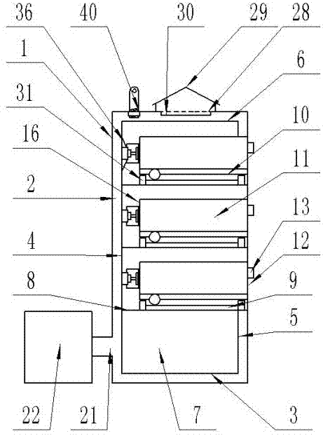
[0023] The present invention is specifically described below in conjunction with accompanying drawing, as Figure 1-7 As shown, an automatic temperature-regulating drawer-type low-voltage power switch cabinet includes a cabinet body 1, the cabinet body 1 is a cuboid, and the cabinet body 1 is composed of a support frame 2 placed on the ground and a rectangular box fixedly installed at the bottom of the support frame 2. Bottom plate 3, the cabinet body left side plate 4 that is positioned at the left side of support frame 2 and is fixedly connected with base plate 3, the cabinet body right side plate 5 that is positioned at support frame 2 right side and is fixedly connected with base plate 3, is positioned at support frame 2 upper ends and is connected with The cabinet top cover 6 fixedly connected to the upper surface of the cabinet left side panel 4 and the cabinet right side panel 5 is located at the rear end of the support frame 2 and is connected to the cabinet bottom pane...


PUM


Abstract

The invention discloses a drawer low-voltage power switchgear cabinet capable of automatically adjusting temperature. The power switchgear cabinet comprises a cuboid cabinet body. A sliding drawer device is arranged in the cabinet body. Vents are uniformly distributed on the surface of the backboard of a drawer. A ventilating device is arranged at the vents. Fan-shaped ventilating channels are arranged on the outer walls of left and right side plates of the cabinet body. Waterproof eaves are welded over the fan-shaped ventilating channels. The position, opposite to the fan-shaped ventilating channels, of the inner wall of the cabinet body is covered with a dust filter net 1. The lower end of the backboard of the cabinet body is provided with an induced draft fan at a position where a circular opening is located. A temperature sensor is arranged on the left side plate of the drawer. An observation window is arranged on the right side plate of the cabinet body. A side of the observation window is provided with a PLC controller, a buzzer and an LED display screen. Uniformly distributed heat dissipation holes are arranged on the top of the top cover of the cabinet body. A conical baffle is fixedly installed above the heat dissipation holes. A dust filter net 2 is fixedly installed on the inner wall of the top cover of the cabinet body and under the heat dissipation holes. The drawer low-voltage power switchgear cabinet is simple in structure and good in practicability.

Description

technical field [0001] The invention relates to the technical field of power equipment, in particular to an automatic temperature-regulating drawer-type low-voltage power switchgear. Background technique [0002] In the field of electric power, the power cabinet is an important tool for storing power components and related control equipment. For the power components and equipment in the power cabinet, it will generate a lot of heat when it is working, which will cause the temperature inside the cabinet to become higher and higher. In order to avoid burning out the power components and equipment, corresponding heat dissipation measures must be taken , to dissipate the heat inside the cabinet in time. At present, in order to realize the heat dissipation of the cabinet body, heat dissipation holes are often provided on the cabinet body, but when the power load increases, the temperature in the cabinet body rises, and the heat dissipation holes alone cannot dissipate the heat q...

Claims


Application Information

Patent Timeline
Patent Type & Authority Applications(China)
IPC IPC(8): H02B11/173H02B1/56H02B1/28H02B1/30
CPCH02B11/173H02B1/28H02B1/30H02B1/565
Inventor 焦彭彭
Owner 焦彭彭
Why Eureka
Try Eureka