Beating device and method for filter cakes and application of filter cakes

A filter cake and driving device technology, applied in chemical instruments and methods, transportation and packaging, dissolving, etc., can solve the problems of easy adhesion of beating paddles, inability to continuously beating, poor beating effect of filter cakes, etc., and achieve short pulping time , practical and safe cleaning, improving effect and efficiency

Active Publication Date: 2017-12-12
CHNA ENERGY INVESTMENT CORP LTD +1
View PDF8 Cites 6 Cited by
  • Summary
  • Abstract
  • Description
  • Claims
  • Application Information

AI Technical Summary

Problems solved by technology

[0009] The object of the present invention is to provide a filter cake beating device and method capable of continuous beating and better beating effect in order to overcome the defects of the prior art that the beating oars are easy to adhere, the filter cake beating effect is poor, and the beating effect cannot be continuous. application

Method used


Image

  • Beating device and method for filter cakes and application of filter cakes
  • Beating device and method for filter cakes and application of filter cakes
  • Beating device and method for filter cakes and application of filter cakes

Examples


Embodiment 1

[0059] This embodiment is used to illustrate the filter cake continuous beating device and method of the present invention and its application.

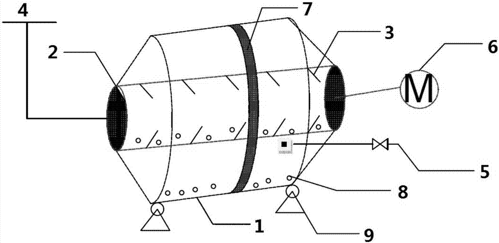
[0060] Such as figure 1 As shown, the filter cake continuous beating device is a horizontal beating device provided with a base 9, wherein the filter cake continuous beating device is provided with a housing 1 and an inner cylinder 2, and the diameter ratio of the inner cylinder 2 and the housing 1 is 1 : 1.2; the inner cylinder 2 is rotatably connected to the housing 1 and is arranged inside the housing 1, and divides the inner cavity of the housing 1 into a first accommodating cavity located inside the inner cylinder 2, and a first accommodating cavity located inside the housing The second accommodating chamber between the body 1 and the inner cylinder 2, the inner cylinder 2 is provided with a material inlet 4 extending to the outside of the housing 1 and communicating with the first accommodating chamber, the side wall of the inn...

Embodiment 2

[0063] This embodiment is used to illustrate the filter cake continuous beating device and method of the present invention and its application.

[0064] Such as figure 1 As shown, the filter cake continuous beating device is a horizontal beating device provided with a base 9, wherein the filter cake continuous beating device is provided with a housing 1 and an inner cylinder 2, and the diameter ratio of the inner cylinder 2 and the housing 1 is 1 : 5; the inner tube 2 is rotatably connected to the housing 1 and is arranged inside the housing 1, and the inner cavity of the housing 1 is divided into a first accommodating chamber located inside the inner tube 2, and a first accommodating cavity located inside the housing The second accommodating chamber between the body 1 and the inner cylinder 2, the inner cylinder 2 is provided with a material inlet 4 extending to the outside of the housing 1 and communicating with the first accommodating chamber, the side wall of the inner cyl...

Embodiment 3

[0067] This embodiment is used to illustrate the filter cake continuous beating device and method of the present invention and its application.

[0068] Such as figure 1 As shown, the filter cake continuous beating device is a horizontal beating device provided with a base 9, wherein the filter cake continuous beating device is provided with a housing 1 and an inner cylinder 2, and the diameter ratio of the inner cylinder 2 and the housing 1 is 1 : 10; the inner cylinder 2 is rotatably connected to the housing 1 and is arranged inside the housing 1, and the inner cavity of the housing 1 is divided into a first accommodating cavity located inside the inner cylinder 2, and a first accommodating cavity located inside the housing The second accommodating chamber between the body 1 and the inner cylinder 2, the inner cylinder 2 is provided with a material inlet 4 extending to the outside of the housing 1 and communicating with the first accommodating chamber, the side wall of the i...


PUM


Abstract

The invention relates to the field of chemical engineering and smelting, and discloses a continuous beating device for filter cakes. The device comprises a shell body and an inner cylinder, the inner cylinder is rotatingly connected with the shell body and is arranged in the shell body, and the inner cylinder divides an inner hollow cavity of the shell body into a first containing cavity located in the inner cylinder and a second containing cavity located between the shell body and the inner cylinder, the inner cylinder is provided with a material inlet which extends to the outside of the shell body and communicates with the first containing cavity, the side wall of the inner cylinder is provided with sieve pores which communicate with the first containing cavity and the second containing cavity, the inner wall of the inner cylinder is provided with a plurality of blades or baffles, the shell body is provided with a filter and a material outlet which communicates with the second containing cavity, and a slurry material which flows out from the material outlet is filtered and discharged by cooperation of the material outlet and the filter located near the material outlet. The invention also discloses an application of the beating device for the filter cakes in a catalyst filter cake beating step and the continuous beating device for filter cakes. According to the invention, the beating device for the filter cakes is adopted, beating is continuously performed, and therefore beating effects and efficiency of the filter cakes can be remarkably improved.

Description

technical field [0001] The invention relates to the fields of chemical industry and smelting, in particular to a filter cake beating device and method and applications thereof. Background technique [0002] In the production process, beating is an important technical link in the slurry preparation process, and this technology is often used in multiple production processes such as papermaking, catalyst preparation, and white carbon black production. Taking catalyst preparation as an example, in the process of catalyst preparation, the slurry is usually filtered to achieve solid-liquid separation, and the formed filter cake may contain some impurity elements or harmful ions that will affect the physical and chemical properties of the catalyst, so The filter cake needs to be beaten with water to form a slurry for washing. [0003] The filter cake usually has high water content, high viscosity, and high solid content. The existing beating systems generally have problems such as...

Claims


Application Information

Patent Timeline
Patent Type & Authority Applications(China)
IPC IPC(8): B01F9/06B01F9/04B02C18/14B02C18/16B02C23/16B01F29/63B01F29/62
CPCB02C18/14B02C18/16B02C23/16B02C2023/165B01F29/30B01F29/4031B01F29/62B01F29/63
Inventor 朱加清孙永伟张琪王传付巴黎明
Owner CHNA ENERGY INVESTMENT CORP LTD
Why Eureka
Try Eureka