Split riprap buoyancy tank

A floating box, split technology, applied in the direction of the hull, foldable/inflatable hull, ships, etc., can solve the problems of severe shaking of the hull, poor stability, and out-of-sync speed and amplitude of opening, so as to improve stability and stability Strong, close-fitting effect

Active Publication Date: 2017-12-12
深圳市蛇口招商港湾工程有限公司
View PDF6 Cites 0 Cited by
  • Summary
  • Abstract
  • Description
  • Claims
  • Application Information

AI Technical Summary

Problems solved by technology

[0004] Although the above-mentioned barge structure unloads quickly, during the unloading process of the barge, since the left half body and the right half body rotate outwards to

Method used


Image

  • Split riprap buoyancy tank
  • Split riprap buoyancy tank
  • Split riprap buoyancy tank

Examples


Embodiment 1

[0038] Embodiment 1, a split riprap floating tank:

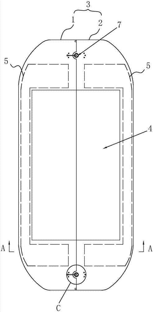
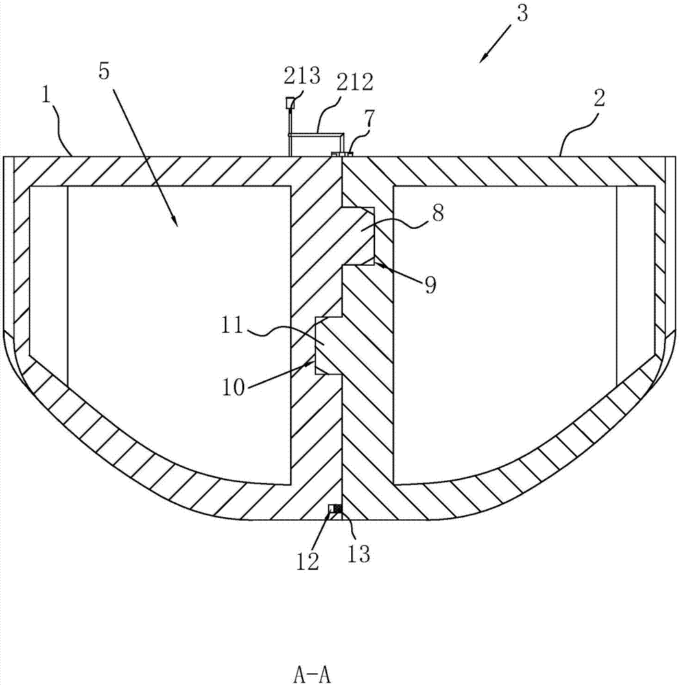
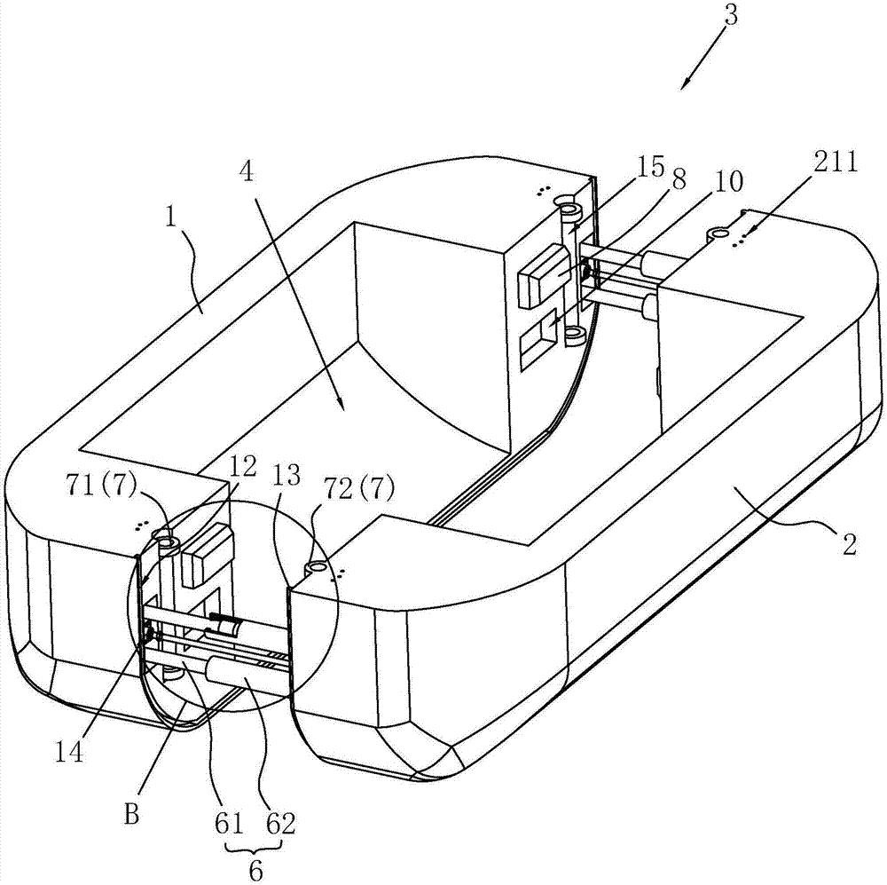
[0039] as attached figure 1 with 3As shown, it includes a buoyancy tank 3 spliced ​​by the left half body 1 and the right half body 2, and a mud tank 4 is arranged in the middle of the buoyant tank body 3, and the bottom surface of the mud tank 4 is a concave arc bottom surface, with a certain The downward slope is conducive to the automatic falling of sand, earth and rocks by gravity. The floating tank body 3 is provided with a driving part 14 for pushing the left half body 1 and the right half body 2 to separate from each other. In the present embodiment, the driving part 14 is a hydraulic cylinder, and the hydraulic cylinder is fixed on the head of the floating tank body of the left half body 1 and On the tail of the floating tank. When the floating tank body 3 needs to be loaded with sand, earth and rocks, the left half body 1 and the right half body 2 are closed to form a complete floating tank body 3, and the left h...

Embodiment 2

[0048] Embodiment 2, a split riprap floating tank:

[0049] The difference between the second embodiment and the first embodiment is that a power system is added in the second embodiment.

[0050] as attached Figure 8 As shown, the tail of the floating tank body 3 is provided with a power system 22, and the power system 22 includes a fixed frame 23, a propeller 24, and a drive motor 25 that drives the propeller 24 to rotate, and the drive motor 25 passes through a turntable 26. It is fixed on the fixed frame 23 and can rotate left and right in a small range, and the propeller 24 is located at the seam position of the left half body 1 and the right half body 2 of the floating tank body 3 .


PUM


Abstract

The invention discloses a split riprap buoyancy tank. According to the technical scheme points, the split riprap buoyancy tank comprises a buoyancy tank body which is formed by splicing of a left half body and a right half body, a mud cabin is arranged in the middle of the buoyancy tank body, empty spaces which are arranged in a sealing mode are arranged both in the position, located on the left side of the mud cabin, of the left half body and the position, located on the right side of the mud cabin, of the right half body; and a rigid connecting assembly and a locking assembly are arranged on the connecting face of the left half body and the right half body, wherein the rigid connecting assembly is used for connecting the left half body and the right half body when the left half body and the right half body are separated, the locking assembly is used for locking the left half body and the right half body when the left half body and the right half body are folded. The split riprap buoyancy tank is simple in structure relative to a stone dumper or a mud boat, the left half body and the right half body have independent floatability, and the buoyancy tank body is high in stability; translation of the right half body is gentle when the buoyancy tank body is separated, and the stability of the buoyancy tank body during unloading is improved; and when the buoyancy tank body is folded, lock and tight folding of the left half body and the right half body can be quickly achieved through the locking assembly, and the split riprap buoyancy tank is more suitable for internal waters of construction sites.

Description

technical field [0001] The invention relates to transportation equipment, in particular to a split riprap floating tank. Background technique [0002] In reclamation or dredging projects, it is often necessary to use artificial, water conservancy, and mechanical means to excavate the sediment and soil from one place and transport it to another place; the transportation of sediment and soil is completed by engineering ships. [0003] For example, the Chinese patent with the publication number 205632942U discloses an open motorized mud barge, which includes a hull, a left half body and a right half body, main girders are arranged on both sides of the hull, and the left half body and the right half body are hinged respectively On the two main girders of the hull. The left half body and the right half body are merged, and the sand, earth and stone can be loaded on the barge; when the designated position is reached, the left half body and the right half body can be opened to rea...

Claims


Application Information

Patent Timeline
IPC IPC(8): B63B7/04
CPCB63B7/04
Inventor 冒盛云陈忠琦
Owner 深圳市蛇口招商港湾工程有限公司
Why Eureka
Try Eureka