Check patentability & draft patents in minutes with Patsnap Eureka AI!

Flying wing aircraft yaw control device based on active flow control technology

An active flow control and heading control technology, applied in the field of aircraft control, can solve problems such as flight accidents, difficulty in heading control, and increasing the weight of the entire aircraft, so as to reduce the quality of the entire aircraft, improve stealth performance, and eliminate adverse effects.

Pending Publication Date: 2017-12-12
NANJING UNIV OF AERONAUTICS & ASTRONAUTICS
View PDF5 Cites 5 Cited by
  • Summary
  • Abstract
  • Description
  • Claims
  • Application Information

AI Technical Summary

Problems solved by technology

[0002] Compared with aircraft with conventional aerodynamic layout, tailless flying wing layout has the advantages of high lift-to-drag ratio, long range, light weight, and low radar scattering area. difficulty
The heading control of the conventional flying wing layout relies on the deflection of the cracked resistance rudder to generate asymmetric aerodynamic resistance, thereby generating the yaw moment, but the yaw moment increment has a nonlinear characteristic with the change of the rudder angle, and the When the angle is too high, it will produce control reversal phenomenon, induce heading oscillation, and cause flight accidents
At the same time, the existence of the rudder surface will bring many problems. In addition to increasing the overall weight of the aircraft and complicated maintenance, it also increases the radar scattering area, reduces the stealth performance of the aircraft, and will cause aerodynamic heating at high speeds. effect, resulting in rudder surface ablation

Method used


Image

  • Flying wing aircraft yaw control device based on active flow control technology
  • Flying wing aircraft yaw control device based on active flow control technology
  • Flying wing aircraft yaw control device based on active flow control technology

Examples


Embodiment Construction

[0026] The present invention will be further described below in conjunction with the accompanying drawings.

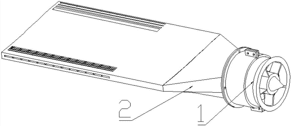
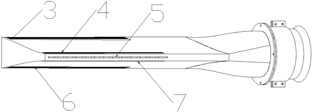
[0027] Such as figure 1 and figure 2 As shown, the flying wing layout aircraft heading control device based on the active flow control technology of the present invention includes a ducted fan 1, an air inlet 2, an upper surface front end air outlet 3, an upper surface rear end air outlet 4, a rear air outlet 5, The air outlet 6 at the front end of the lower surface, the air outlet 7 at the rear end of the lower surface, the air outlet 8 at the rear, and the airflow guide 9, wherein the ducted fan 1 and the air inlet 2 are fixed together by screws, and the airflow guide 9 is arranged on the fly The wings lay out the front and rear ends of the interior of the aircraft heading control unit.

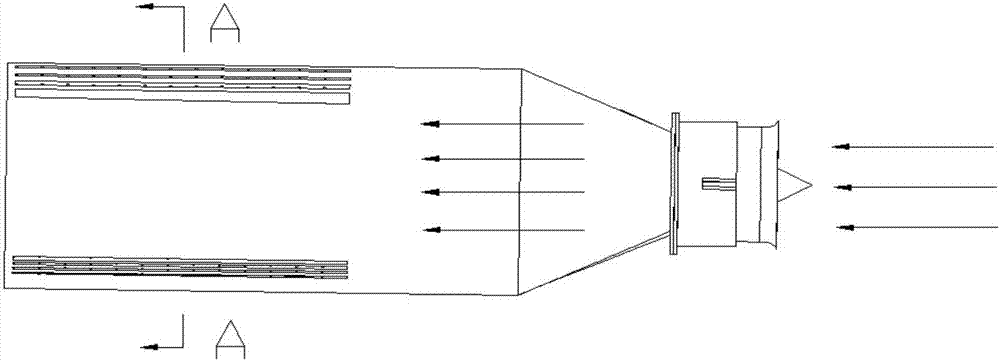
[0028] Such as image 3 and Figure 4 As shown, after the ducted fan is turned on, the airflow enters from the air inlet 2 and is ejected along the airflow guide fins 9 distrib...


PUM


Abstract

The invention discloses a flying wing aircraft yaw control device based on an active flow control technology. The flying wing aircraft yaw control device comprises a ducted fan, an air inlet channel, an upper surface front end air outlet, an upper surface rear end air outlet, a rear air outlet, a lower surface front end air outlet, a lower surface rear end air outlet, another rear air outlet and airflow guiding pieces. The ducted fan and the air inlet channel are fixed together through screws, and the airflow guiding pieces are arranged at the front and the rear ends of the interior of the flying wing aircraft yaw control device. Yaw control over a flying wing aircraft can be effectively achieved through different air-blowing motivation forms. The flying wing aircraft yaw control device has the advantages that a traditional flying wing aircraft yaw control component, namely a cracking type drag rudder, can be replaced, rudder-free yaw control is achieved, and the active flow control device is higher in response speed, simpler in structure, lower in weight and convenient to install and maintain.

Description

Technical field: [0001] The invention relates to a heading control device for a flying-wing layout aircraft based on active flow control technology, and belongs to the technical field of aircraft control. Background technique: [0002] Compared with aircraft with conventional aerodynamic layout, tailless flying wing layout has the advantages of high lift-to-drag ratio, long range, light weight, and low radar scattering area. difficulty. The heading control of the conventional flying wing layout relies on the deflection of the cracked resistance rudder to generate asymmetric aerodynamic resistance, thereby generating the yaw moment, but the yaw moment increment has a nonlinear characteristic with the change of the rudder angle, and the When the angle is too high, it will produce control reversal phenomenon, induce heading oscillation, and cause flight accidents. At the same time, the existence of the rudder surface will bring many problems. In addition to increasing the ove...

Claims


Application Information

Patent Timeline
IPC IPC(8): B64C15/02
CPCB64C15/02Y02T50/10
Inventor 史志伟朱佳晨耿玺董益章周志鹏孙琪杰
Owner NANJING UNIV OF AERONAUTICS & ASTRONAUTICS
Features
  • R&D
  • Intellectual Property
  • Life Sciences
  • Materials
  • Tech Scout
  • Unparalleled Data Quality
  • Higher Quality Content
  • 60% Fewer Hallucinations
Learn More