Traffic cone recovery device for automatic traffic cone collection and placement vehicle

An automatic retractable and recycling device technology, applied in traffic signals, roads, roads and other directions, can solve problems such as unobvious practical significance, dangerous driving mode, and low process efficiency, so as to improve timeliness and accuracy and reduce recycling work risk, the effect of increasing speed

Pending Publication Date: 2017-12-12
SHANDONG UNIV OF TECH
View PDF3 Cites 8 Cited by
  • Summary
  • Abstract
  • Description
  • Claims
  • Application Information

AI Technical Summary

Problems solved by technology

[0004] Chinese patent application 201310403155.5 discloses a "special vehicle for automatically retracting and storing traffic cones", which includes a retractable device for retracting and retracting traffic cones installed at the rear of the vehicle. The device is used to collect the traffic cones. Although the device can realize the recovery function of the traffic cones, the whole process of recovering the traffic cones needs to be driven in reverse, which is obviously a dangerous driving mode on the highway or the congested urban road.
This device can only collect passing traffic cones one by one in order, and the process efficiency is low
[0005] Chinese patent applications 201420096133.9 and 201610902238.2 disclose a "manipulator for grabbing traffic cones" and "a traffic cone pick-up device", which mainly uses splints to fix and clamp the base of traffic cones. Although this mechanism can realize the grasping of traffic cones However, since the traffic cones are placed upright on the road surface, the device cannot grasp the upright traffic cones, so the practical significance of the mechanism for the entire process of automatic collection of traffic cones is not obvious

Method used


Image

  • Traffic cone recovery device for automatic traffic cone collection and placement vehicle
  • Traffic cone recovery device for automatic traffic cone collection and placement vehicle
  • Traffic cone recovery device for automatic traffic cone collection and placement vehicle

Examples


Embodiment Construction

[0016] Below by embodiment and in conjunction with accompanying drawing, the present invention will be further described:

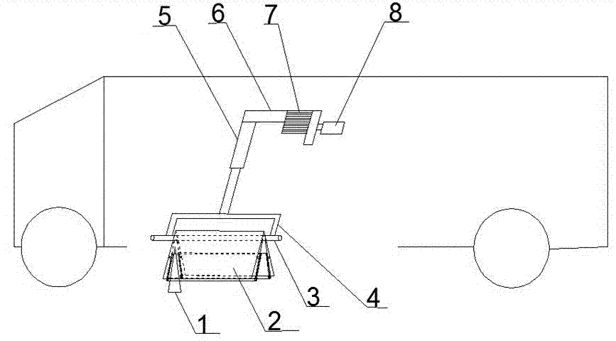
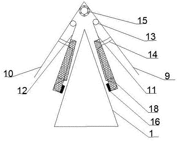
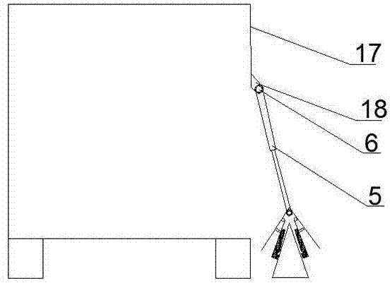
[0017] to combine figure 1 — Figure 6 As shown, a road cone recovery device for a traffic cone automatic retractable vehicle is mainly composed of a traffic cone 1, a clamp 2, a first mandrel 3, a U-shaped connecting arm 4, a hydraulic telescopic arm 5, a second mandrel 6, and a gear Surface 7, stepper motor 8, right outer splint 9, left outer splint 10, right inner splint 11, left inner splint 12, inner splint wall 18, hinge link 13, hydraulic cylinder 14, third mandrel 15, microwave radar sensor Device 16, car body 17, circular hole 18 form.

[0018] Right outer splint 9 and left outer splint 10 joints are welded and fixed, and ball bearings are housed in the two outer splints joint inner bearing sleeves, and a third mandrel 15 is passed through the ball bearings. The right inner splint 11 is hinged to the right outer splint 9, and a hydraulic cylin...


PUM


Abstract

A road cone recovery device for a traffic cone automatic retractable vehicle, including a clamp, the clamp includes a left outer splint, a right inner splint, a left inner splint, an inner splint wall, a hinge, a hydraulic cylinder, a microwave radar sensor, and the clamp and The first mandrel is connected with the U-shaped connecting arm, the U-shaped connecting arm is connected with the hydraulic telescopic arm, the hydraulic telescopic arm is connected with the second mandrel, and the gear surface at the end of the second mandrel is in contact with the gear surface of the stepping motor. When working, the microwave radar sensor senses the position of the traffic cone, the clamp fixes the traffic cone, the hydraulic telescopic arm shrinks to lift the traffic cone fixed by the clamp connected to the U-shaped connecting arm, and the stepping motor drives the hydraulic telescopic arm connected to the second mandrel to rotate , Transport the traffic cone to the designated location, the whole process does not require manual participation. A plurality of devices of the present invention are arranged outside the traffic cone automatic retractable vehicle to recover the traffic cones and improve work efficiency.

Description

technical field [0001] The invention relates to the technical field of automatic recovery equipment for traffic cones in road construction, in particular to a road cone recovery device for a traffic cone automatic retractable vehicle. Background technique [0002] When placing and collecting road traffic cones, usually 2 to 3 construction workers place or recover the traffic cones one by one along the specific placement or recovery route of the traffic cones. This working method is inefficient and The risk factor of the operation is high, and the labor cost is increased at the same time. At present, some domestic enterprises are developing and researching the road cone recovery equipment of the automatic retractable vehicle for traffic cones, but the developed equipment always has the problems of low work efficiency and unstable grasping of traffic cones. [0003] Existing workarounds: [0004] Chinese patent application 201310403155.5 discloses a "special vehicle for auto...

Claims


Application Information

Patent Timeline
Patent Type & Authority Applications(China)
IPC IPC(8): E01F9/70
CPCE01F9/70
Inventor 石沛林吕少文冯晓志徐国辉邹宏骏苗立东张为春赵强吕世柱王佳慧
Owner SHANDONG UNIV OF TECH
Why Eureka
Try Eureka