

Method and device for locking laser wavelength for gas detection
A laser wavelength and gas detection technology, applied in the measurement of color/spectral characteristics, analysis of materials, instruments, etc., can solve the problem that the spectroscopic scheme cannot be applied to spatial scanning, affects the measurement accuracy of the system, and the optical path is unstable, so as to solve the problem of measurement accuracy. , Improve the light intensity, solve the effect of waste of resources
- Summary
- Abstract
- Description
- Claims
- Application Information
AI Technical Summary
Problems solved by technology
Method used
Image

Examples
Embodiment 1
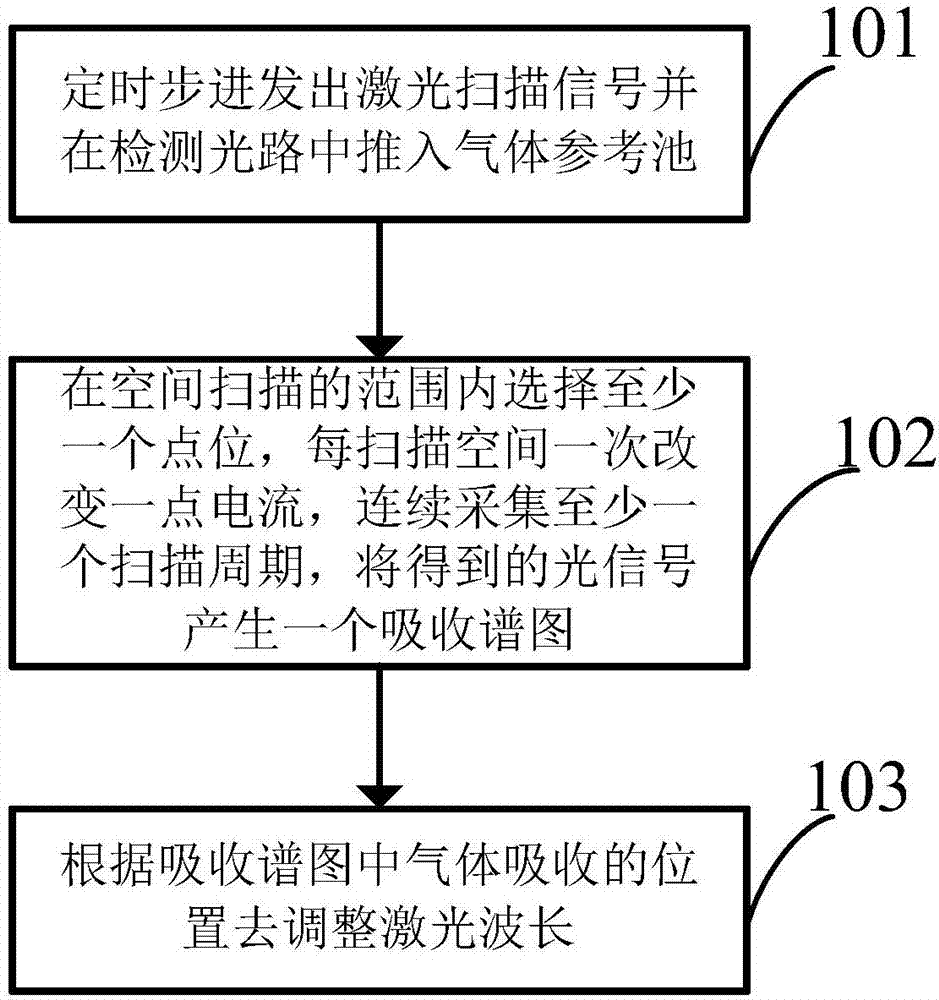
[0035] refer to image 3 As shown, a laser wavelength locking method for gas detection disclosed in an embodiment of the present invention includes the following steps:
[0036] Step 101, sending out a laser scanning signal step by step at regular intervals and pushing the gas reference cell into the detection optical path;
[0037] Step 102, select at least one point within the range of spatial scanning, change a little current every time the space is scanned, collect at least one scanning cycle continuously, and generate an absorption spectrum from the obtained optical signal;
[0038] Step 103, adjusting the laser wavelength according to the gas absorption position in the absorption spectrum.
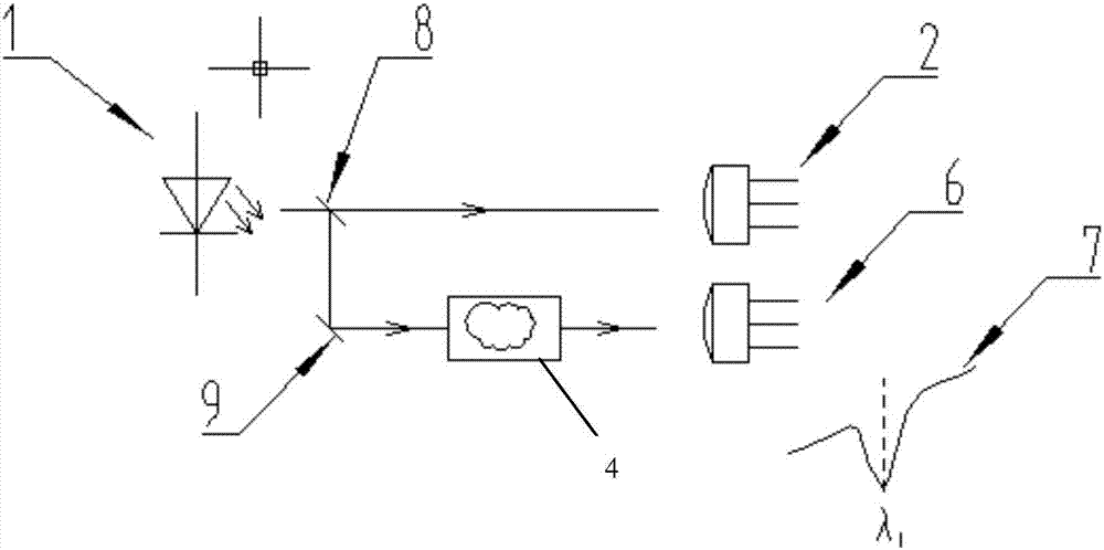
[0039] Compared with the original spectroscopic scheme, the present invention reduces a set of laser spectroscopic devices and a set of reference light detection circuits, and the light intensity output by the laser can be used for detection, which is beneficial to long-distance det...
Embodiment 2
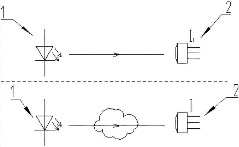
[0052] Corresponding to the above method, refer to Figure 5 As shown, the embodiment of the present invention also provides a laser wavelength locking device for gas detection, the device is used to implement the above wavelength locking method, the device includes: a laser 1, a detector 2, a gas absorption cell 3, a motor The push rod 4 and the control module 5, wherein the control module 5 is respectively connected to the laser 1, the electric push rod 4 and the detector 2, the laser 1 and the detector 2 are arranged in parallel, and the light intensity emitted by the laser 1 is Received by the detector 2, the detector 2 feeds back the light intensity to the control module 5, and the control module 5 gives an instruction to the electric actuator 4 when wavelength adjustment or wavelength position detection is required, and controls The electric push rod 4 moves to push the gas absorption cell 3 into the detection optical path between the laser and the detector. At the same ...
PUM
 Abstract
Description
Claims
Application Information