PCM (pulse code modulation) switch alarming device
An alarm device and switch technology, applied in the field of electrical communication, can solve problems such as inconvenient maintenance, and achieve the effects of easy detection and maintenance, fast response, and high sensitivity
- Summary
- Abstract
- Description
- Claims
- Application Information
AI Technical Summary
Problems solved by technology
Method used
Image

Examples
Embodiment 1
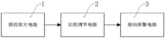
[0017] exist figure 1 Among them, a PCM switch alarm device, including a receiving amplifier circuit 1, a comparison adjustment circuit 2 and a drive alarm circuit 3, the receiving amplifier circuit 1 receives the PCM switch signal and is controlled by the comparison adjustment circuit 2 using a double op amp after comparison and adjustment. The driving alarm circuit 3, because the analysis of the single-chip microcomputer is replaced by the analysis of the single-chip microcomputer to directly control the driving alarm circuit, the high sensitivity of the single-chip microcomputer is retained, and the response is fast, which is convenient for detection and maintenance;
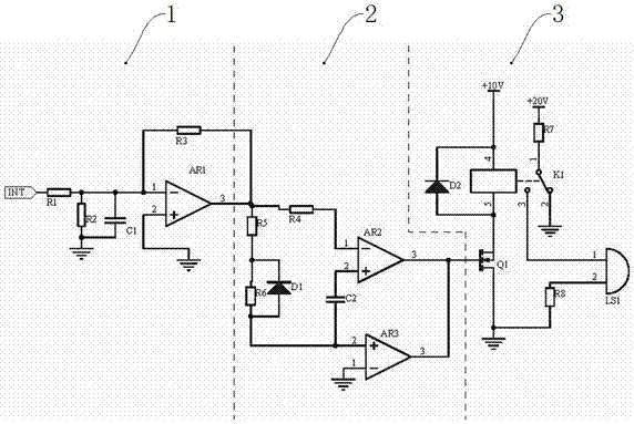
[0018] like figure 2 As shown, the receiving amplifying circuit 1 receives the PCM signal through the voltage division of resistors R1 and R2 and filters the RC circuit composed of resistor R1 and capacitor C1. One end of R1-R3 and one end of capacitor C1, the other end of resistor R1 is connected to the si...
Embodiment 2
[0020] like figure 2 As shown, on the basis of Embodiment 1, the comparison and adjustment circuit 2 uses the common output terminals of the operational amplifiers AR2 and AR3, the capacitor C2 is connected to the non-inverting input terminals of the operational amplifiers AR2 and AR3, and the inverting input terminal of the operational amplifier AR2 passes through Resistor R4 receives the signal amplified by amplifier circuit 1, and the non-inverting input terminals of op amps AR2 and AR3 receive the signals after voltage division by resistors R5 and R6. Op amps AR2 and AR3 compare and output stable signals. If the signals are abnormal, compare and adjust the circuit The signal output by 2 can make the MOS tube Q1 conduct, and then the relay K1 is energized, and the alarm LS1 works and alarms. If the signal is abnormal, the signal output by the comparison adjustment circuit 2 will not make the MOS tube Q1 conduct, and the alarm LS1 will not work. ; The inverting input termin...
PUM
 Abstract
Description
Claims
Application Information
 - R&D
- Intellectual Property
- Life Sciences
- Materials
- Tech Scout
- Unparalleled Data Quality
- Higher Quality Content
- 60% Fewer Hallucinations
Browse by: Latest US Patents, China's latest patents, Technical Efficacy Thesaurus, Application Domain, Technology Topic, Popular Technical Reports.
© 2025 PatSnap. All rights reserved.Legal|Privacy policy|Modern Slavery Act Transparency Statement|Sitemap|About US| Contact US: help@patsnap.com