High-precision venous drainage device

A high-precision, venous technology, used in suction devices, hypodermic injection devices, extraction and pumping systems, etc., can solve the problems of inaccurate pressure control and difficulty in negative pressure adjustment, improve stability and accuracy, and prevent danger. , to avoid damaging effects

Active Publication Date: 2017-12-15
BEIJING UNIV OF TECH
View PDF16 Cites 0 Cited by
  • Summary
  • Abstract
  • Description
  • Claims
  • Application Information

AI Technical Summary

Problems solved by technology

[0004] Patent CN202376607U provides a low negative pressure continuous flushing device, which is designed to be close to the clinic, relying on multi-pipe pressure partial pressure and connecting to the atmosphere to achieve negative pressure pressure control, to a certain extent avoiding damage caused by improper human operation, negative pressure It is difficult to adjust the pressure, the pressure control is not accurate enough, and the scope of application is limited to the aspects of effusion, wound surface attraction, etc.

Method used


Image

  • High-precision venous drainage device
  • High-precision venous drainage device
  • High-precision venous drainage device

Examples


Embodiment 1

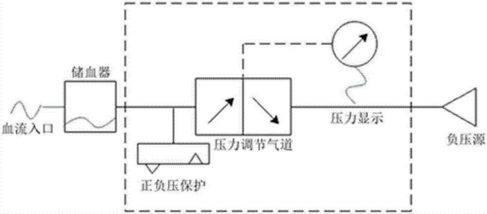
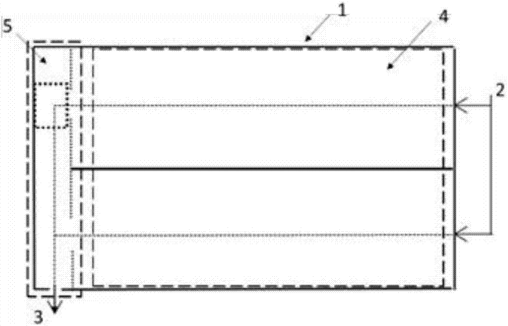
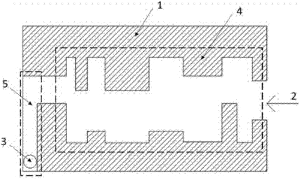
[0027] Example 1 The pressure-adjusting airway 1 of the high-precision venous drainage device adopts two sections of eddy current decompression airway 4 in parallel to realize negative pressure pressure control, and the negative pressure source is connected to the entrance of eddy current decompression airway 4, which is the negative pressure source inlet a2 , the gas is output from the negative pressure output port a3 after passing through the vortex decompression air channel 4 and the air channel control 5 . The output port is connected with a blood storage device, and the blood storage device is connected with a negative pressure interface during venous drainage of the human body. A pressure sensor and positive and negative pressure protection are fixed at the negative pressure output port, and the pressure sensor transmits the acquired pressure to the panel for display. The pressure regulating airway 1 is composed of two parallel decompression airways;

[0028] The vortex...

Embodiment 2

[0034] Example 2 is independent of Example 1. The difference is that in Example 2, the pressure-regulating airway 1 uses a spiral airway, namely the swirling flow decompression airway 6, to realize negative pressure control, and the negative pressure source is connected to the swirling flow decompression airway 6 inlet, which is the negative pressure source The gas is connected to the port b7, and the gas is output from the negative pressure output port b8 after passing through the area of ​​the swirling flow decompression air channel 6 and the central cylinder 9. The output port is connected with a blood storage device, and the blood storage device is connected with a negative pressure interface during venous drainage of the human body. A pressure sensor and positive and negative pressure protection are fixed at the negative pressure output port, and the pressure sensor transmits the acquired pressure to the panel for display.

[0035]The swirling flow decompression airway 6...


PUM


Abstract

The invention discloses a high-precision venous drainage device. The device comprises an external panel, a negative pressure source access port, a pressure regulating airway, a negative pressure outlet, an airway control switch and a visible pressure display device; the pressure regulating airway can control the negative pressure in a high-precision mode; the pressure regulating airway then adjusts and controls the pressure through formed specific vortexes; the device has the positive and negative pressure protection function, that is, positive pressure protection and high negative pressure protection are provided, and risks in the use process are prevented. By means of the device, the venous blood drainage amount can be increased only by loading a stable negative pressure source to a closed blood storage device, and the method is simple and convenient to use. Except that small venous cannulas can be used and tissue injury is reduced, the pipeline of a cardiopulmonary bypass device (CPB) can be miniaturized, the priming volume of the CPB is thus reduced, the blood dilution degree is significantly reduced, and the platelet consumption is reduced.

Description

technical field [0001] The invention relates to a venous drainage device, in particular to a venous drainage device with adjustable negative pressure. Background technique [0002] During cardiopulmonary bypass (CPB) cardiac repair, the heart draws blood from the superior vena cava (VS), inferior vena cava (VCI) or atrium through one or more venous catheters into the oxygenator and the blood pump back to itself due to negative pressure artery. In practice, due to different arterial blood flow and return flow, the fixed negative pressure provided by the negative pressure source is not enough to meet the individual needs of the current operation. It is necessary to design and manufacture a negative pressure adjustment device for venous drainage. [0003] Patent CN202143745U is a transparent negative pressure drainage device for arterialized venous flaps. It uses medical self-adhesive and medical sponge to form a negative pressure drainage area. After connecting to a negative ...

Claims


Application Information

Patent Timeline
Patent Type & Authority Applications(China)
IPC IPC(8): A61M1/00
CPCA61M1/0023A61M2202/0413A61M1/74A61M2202/0021
Inventor 常宇杨佳音石悦付天翔
Owner BEIJING UNIV OF TECH
Why Eureka
Try Eureka