
Horizontal force supporting mechanisms for working rollers of eighteen-roller mill

A support mechanism and technology for work rolls, applied in the direction of metal rolling mill stand, metal rolling stand, metal rolling, etc., can solve the problems of affecting the bending effect of intermediate rolls, difficulty in horizontal movement of work rolls, and huge side support structures, etc. , to achieve the effects of enhancing applicability and universality, increasing return on investment, and expanding varieties

Pending Publication Date: 2017-12-15
WISDRI ENG & RES INC LTD
View PDF4 Cites 3 Cited by
  • Summary
  • Abstract
  • Description
  • Claims
  • Application Information

AI Technical Summary

Problems solved by technology

There are mainly two types of side support for the existing 18-high rolling mill. One of them is to directly push the side support roll box forward to the working position through the hydraulic cylinder to support the work roll. This kind of scheme is difficult to design the horizontal movement of the work roll. All the horizontal force is borne by the side support, the side support structure is huge, and the internal space of the rolling mill is small, so when replacing the side support backing bearing, it is necessary to completely remove the work roll and the intermediate roll from the frame to replace the side support roll box , time-consuming and labor-intensive, which affects production efficiency; the other is to hang the side support on the middle bearing seat, and the side support beam pushes the side support to rotate, and then presses the work roll as the support of the horizontal force. At the same time, it is realized by the side support rotation Work roll horizontal movement and roll diameter compensation function, but when replacing the side support backing bearing, the middle roll needs to be removed from the frame, and the cumbersome and complicated off-line disassembly and assembly work is carried out. In addition, because the side support is suspended on the middle roll bearing seat, The side support will move when the intermediate roll needs to be bent, but at this time the side support beam tightly bears against the side support on the work roll, and there will be interference between the side support roll and the work roll or relative sliding under large positive pressure , which affects the bending effect of the intermediate roll, and at the same time increases the wear of the roll surface, reduces the life of the roll, and increases the investment cost

Method used


Image

  • Horizontal force supporting mechanisms for working rollers of eighteen-roller mill
  • Horizontal force supporting mechanisms for working rollers of eighteen-roller mill

Examples


Embodiment Construction

[0028] Shown below Figure 1-2 Embodiments of the present invention are further described:

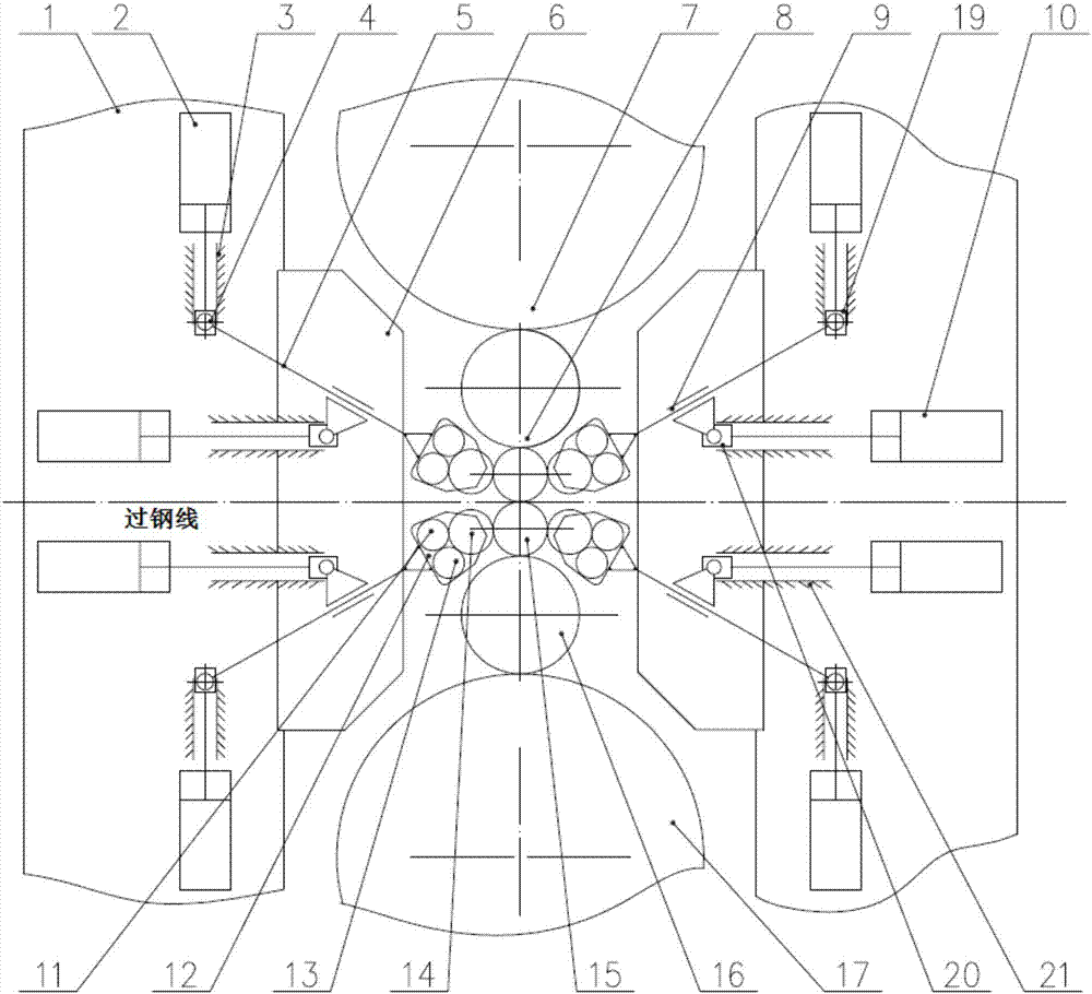
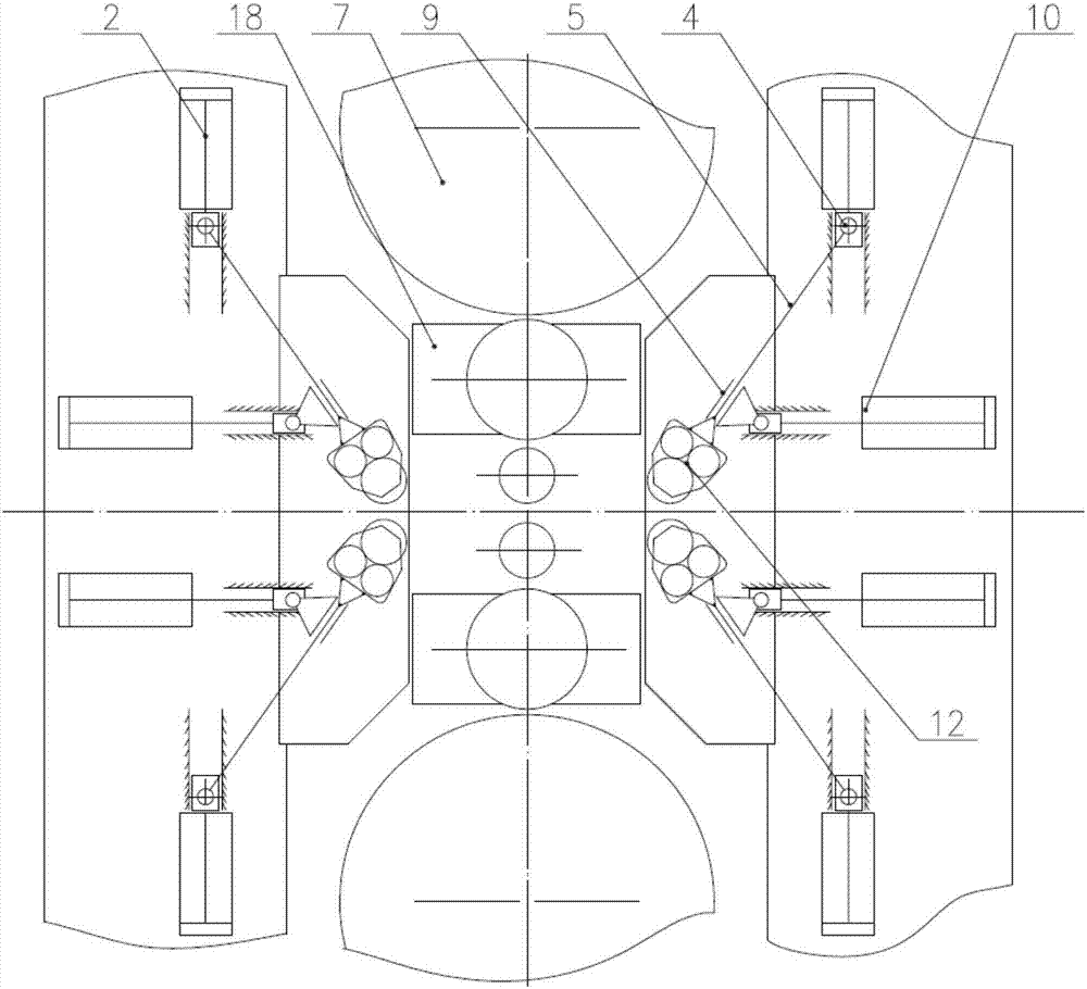
[0029] In the present invention, the eighteen-high rolling mill is a cold rolling mill for rolling metal strips. In order to reduce the horizontal deflection of the work roll 15, lateral supports are added on both sides of the work roll 15, and the lateral support is a connecting rod. The slider structure can approach and finally support the work roll 15 along the fitting path under the action of the vertical push-pull hydraulic cylinder 2 (displacement sensor is installed inside) and the horizontal push-pull hydraulic cylinder 10 . The specific structure of its lateral support is as follows: the vertical push-pull hydraulic cylinder 2 is installed on the inner side of the frame archway 1, and its piston rod is connected with the vertical slider 19, and the vertical slider 19 can be fixed on the frame archway 1. Slideway 3 slides up and down, is designed with rotating hinge shaft 4 on...


PUM


Abstract

The invention relates to horizontal force supporting mechanisms for working rollers of an eighteen-roller mill. The horizontal force supporting mechanisms are arranged at inlets and outlets of all the working rollers in pairs and symmetrically arranged with respect of a steel passing line of the eighteen-roller mill. The horizontal force supporting mechanisms are characterized by comprising vertical push-pull hydraulic cylinders and horizontal push-pull hydraulic cylinders; every two push-pull hydraulic cylinders form a connection rod and slide block structure; the tail end of each connection rod and slide block structure is provided with a side supporting roller box which mainly comprises a main backing bearing, an auxiliary backing bearing, a side supporting rollers and a roller box frame; and during working, the side supporting rollers make contact with the working rollers, horizontal force of rolling is transmitted through the side supporting rollers and received by the corresponding two push-pull hydraulic cylinders. Thus, the eighteen-roller mill is more reasonable in inner structure layout, convenient and quick in roller replacement and more flexible in control.

Description

technical field [0001] The invention belongs to the field of metallurgical equipment, and in particular relates to a novel horizontal force support mechanism for working rolls of an 18-high rolling mill. Background technique [0002] The 18-high rolling mill is an important model for producing cold-rolled strip steel. It has obvious advantages in rolling difficult-to-deform materials and extremely thin strips. By moving the work roll horizontally and adding side support structures on both sides of the work roll, it is ensured that the horizontal deflection of the work roll during rolling is within the allowable range. Because the side support structure has to bear a relatively large horizontal force, its structure is relatively thick and strong, and to contact with the work rolls, it is necessary to choose rolls that can rotate with each other for direct support. There are mainly two types of side support for the existing 18-high rolling mill. One of them is to directly pus...

Claims


Application Information

Patent Timeline
Patent Type & Authority Applications(China)
IPC IPC(8): B21B13/02B21B31/02
CPCB21B13/02B21B31/02B21B2013/028
Inventor 邵远敬尉强叶理德陈洁孙光红
Owner WISDRI ENG & RES INC LTD
Learn More