Waste cable material separating and recycling device

A waste cable, separation and recycling technology, used in cable installation devices, cable installation, electronic waste recycling and other directions, can solve problems such as increased recycling workload, inability to achieve online peeling, hand injuries, etc.

Active Publication Date: 2017-12-15
南通市东风特种电线有限公司
View PDF7 Cites 19 Cited by
  • Summary
  • Abstract
  • Description
  • Claims
  • Application Information

AI Technical Summary

Problems solved by technology

[0005] The disadvantages of the above two structures are: when in use, it is necessary to manually pull and cooperate to realize t...

Method used


Image

  • Waste cable material separating and recycling device
  • Waste cable material separating and recycling device
  • Waste cable material separating and recycling device

Examples


Embodiment 1

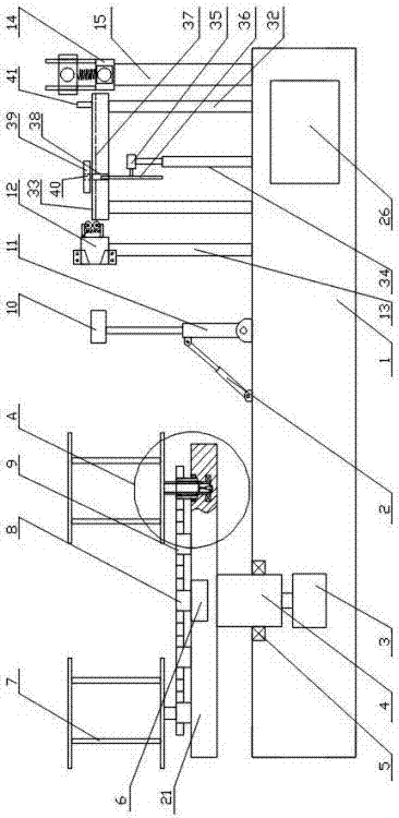
[0049] A waste cable material separation and recovery device, comprising a base 1, a winding mechanism arranged on the base 1, three lead wire mechanisms arranged on the base 1 and matched with the winding mechanism, arranged on the base 1 and the peeling mechanism that matches with the three lead wire mechanisms, the guide mechanism that is arranged on the base 1 and cooperates with the peeling mechanism, is arranged on the base 1 and is located between the peeling mechanism and the A cutting mechanism between the guiding mechanisms, and a control mechanism 26 arranged on one side of the base for coordinated control of the winding mechanism, lead wire mechanism, peeling mechanism, guiding mechanism and cutting structure;

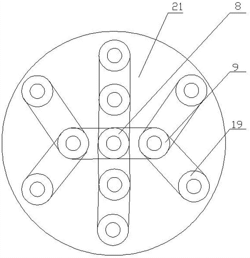
[0050] The winding mechanism includes a rotating shaft 4 arranged on the base 1, a rotating platform 21 arranged on the rotating shaft 4, a plurality of winding modules arranged on the rotating platform 21, and the winding module A transmission mechanism th...

Embodiment 2

[0068] It differs from Embodiment 1 in that:

[0069] A guide plate 129 for guiding the outer skin is provided on the annular tool holder 124 .

[0070] The upper half of the lead rod 11 is provided with a third telescopic rod.

[0071] The telescopic rod 22 is an electric telescopic rod with a rotary joint 23 at the bottom, and a brush is provided at the lower end of the electric telescopic rod.

[0072] A lever cylinder 41 for temporarily pressing and fixing waste cables is arranged on the upper part of the wire pressing plate 39 close to the position of the guiding mechanism.

[0073] The guide plate used in this embodiment is a rectangular slot, which can well control the cut skin, avoid disorder, and achieve more precise length control. The third telescopic rod used is an electric telescopic rod. When the lead wire is wound, the winding position of the sheath or the metal wire core can be controlled through the expansion and contraction of the third telescopic rod, so a...

Embodiment 3

[0075] Such as Figure 10-12 As shown: the difference between it and the second embodiment is that: the bottom of the base 1 is provided with a walking wheel 27, and the rotating platform 21 is provided with four first positioning protrusions 28 for positioning, and the base 1 is provided with The first positioning switch 31 matched with the first protrusion 28, and the first positioning switch 31 is interconnected with the control mechanism 26;

[0076] Four second positioning projections 29 for positioning are arranged on the lower end surface of the winding wheel, and a second positioning switch 30 matched with the second positioning projections 29 is provided on the rotating platform 21, and The second positioning switch 30 is connected to the control mechanism 26 for signals.

[0077] The first positioning protrusion and the second positioning protrusion adopted in this embodiment are all four-sided platforms; and the first positioning protrusion adopted can also be arra...


PUM


Abstract

The invention provides a waste cable material separating and recycling device comprising a base, a winding mechanism arranged on the base, a plurality of leading mechanisms arranged on the base and matched with the winding mechanism, a peeling mechanism arranged on the base and matched with the leading mechanisms, a guide mechanism arranged on the base and matched with the peeling mechanism, a cutting mechanism arranged on the base and located between the peeling mechanism and the guiding mechanism and a controlling mechanism arranged on one side of the base and used for coordinating and controlling the winding mechanism, the leading mechanism, the peeling mechanism, the guide mechanism and the cutting mechanism. The winding mechanism, the leading mechanisms and the cutting mechanism are arranged on the base. In order to avoid the phenomenon that during peeling, cable materials are instable, the guide mechanism is arranged in front of the peeling mechanism, mutually cooperative work of all the components is achieved through coordination of the control mechanism, rapid separation and cutting can be better conducted, metal and peels are separately stored, and therefore recycling of waste is achieved.

Description

technical field [0001] The invention relates to the technical field of waste and old cable material separation and recovery devices, in particular to a waste and old cable material separation and recovery device. Background technique [0002] With the continuous development of the national economy and the strong advocacy of environmental protection, mechanical equipment using coal and petroleum as raw materials is gradually being replaced by electrical equipment, such as electric boilers, electric vehicles, etc. The changes in the structure of such products are invisible. The rapid increase in the demand for electricity caused by electricity, so electric power-related companies have developed a variety of high-load, high-power transmission equipment to meet the needs of the current situation. Among them, the promotion and use of overhead transmission lines with insulated cables has effectively avoided the failure of ordinary transmission lines Many problems, such as large en...

Claims


Application Information

Patent Timeline
IPC IPC(8): B65H54/70B65H57/14H01B15/00H02G1/12
CPCB65H54/70B65H57/14B65H2701/34H01B15/00H01B15/005H02G1/1248H02G1/127Y02W30/82
Inventor 裴天锋
Owner 南通市东风特种电线有限公司
Why Eureka
Try Eureka