Centrally-feeding swirl pulverized coal combustion device adopting double-layer jet flow of separated secondary air

A pulverized coal combustion and pulverized coal burner technology, applied in the direction of burners, combustion methods, combustion types, etc., can solve the problems of poor emission reduction effect, furnace slagging, etc., and achieve strong air classification, enhanced reducibility, and coal adaptable effect

Inactive Publication Date: 2017-12-15
HARBIN INST OF TECH
View PDF7 Cites 4 Cited by
  • Summary
  • Abstract
  • Description
  • Claims
  • Application Information

AI Technical Summary

Problems solved by technology

[0006] The present invention aims to solve the problem of the existing pulverized coal combustion device under the conditions of variable coal types and variable loads. x The emission reduction effect is poor, and it is easy to cause the problem of slagging in the furnace, and then provide a center-feeding swirling pulverized coal combustion device that uses separated secondary air double-layer jets

Method used


Image

  • Centrally-feeding swirl pulverized coal combustion device adopting double-layer jet flow of separated secondary air
  • Centrally-feeding swirl pulverized coal combustion device adopting double-layer jet flow of separated secondary air
  • Centrally-feeding swirl pulverized coal combustion device adopting double-layer jet flow of separated secondary air

Examples


specific Embodiment approach 1

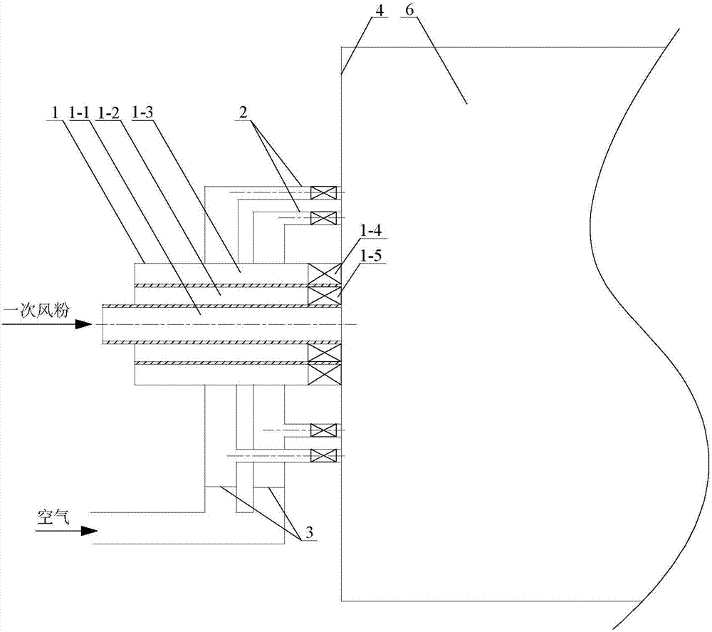
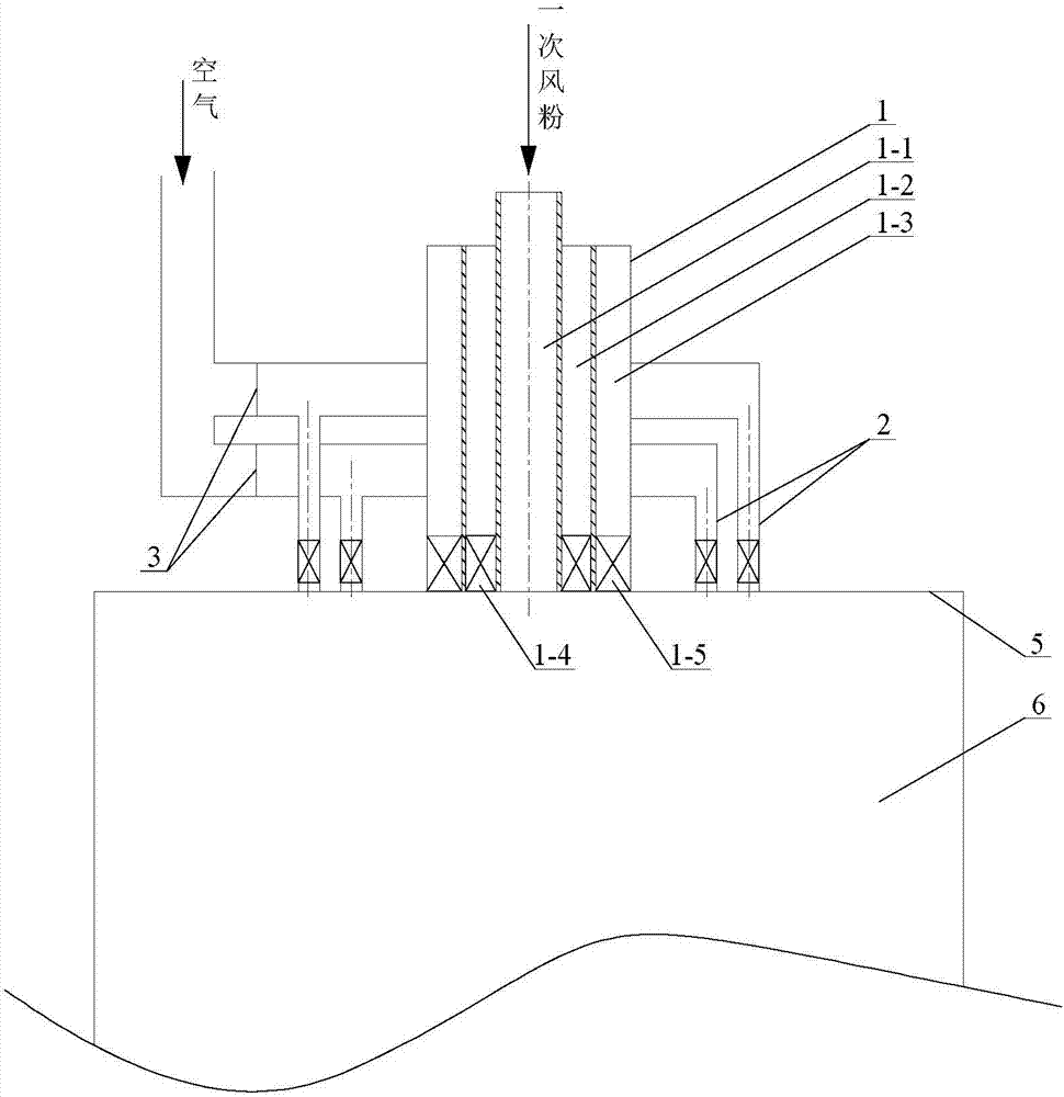
[0024] Specific implementation mode one: as Figure 1~2 As shown, the center-feeding swirl pulverized coal combustion device using separated secondary air double-layer jets in this embodiment includes a swirl pulverized coal burner 1, a plurality of separated secondary air pipes 2 and a plurality of separated secondary windshields Plate 3; the swirl pulverized coal burner 1 is arranged on the front wall 4 of the boiler or is located on the roof 5 of the vertical boiler, and the swirl pulverized coal burner 1 includes a primary air duct 1-1, a secondary air duct in the swirl The air duct 1-2 and the secondary air duct 1-3 outside the swirl, the primary air duct 1-1 is arranged in the secondary air duct 1-2 inside the swirl and is located in the secondary air duct 1-2 inside the swirl Center position, the secondary air duct 1-2 inside the swirl is set in the secondary air duct 1-3 outside the swirl, the primary air duct 1-1, the secondary air duct 1-2 inside the swirl and the ou...

specific Embodiment approach 2

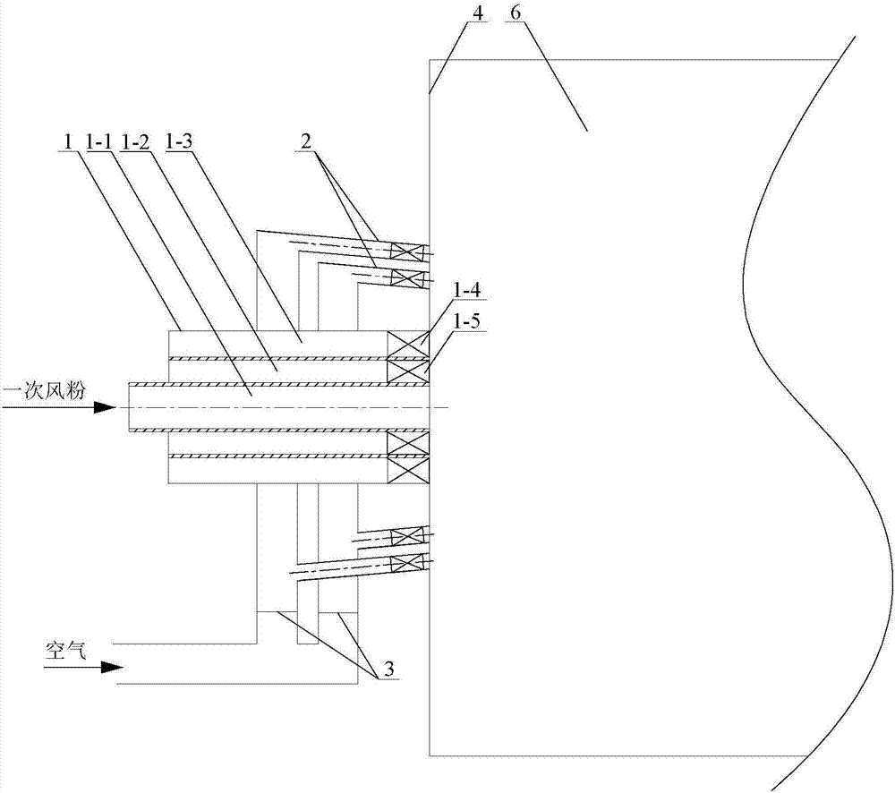
[0026] Specific implementation mode two: as image 3As shown, the angle between the axis of the separated secondary air duct 2 and the inner wall of the furnace in this embodiment is adjustable, and the angle between the axis of the separated secondary air duct 2 and the axis of the swirl pulverized coal burner 1 is ±30 °. Such a design makes the separated secondary air form a rotating jet and enter the furnace 6 . Other components and connections are the same as those in the first embodiment.

specific Embodiment approach 3

[0027] Specific implementation mode three: as Figure 1~3 As shown, in this embodiment, the first axial swirl blades 1-4 are arranged on a side close to the inner wall of the furnace 6 . With such a design, the swirl strength in the secondary air pipe 1-3 outside the swirl can be adjusted. Other compositions and connections are the same as those in Embodiment 1 or 2.


PUM


Abstract

The invention discloses a centrally-feeding swirl pulverized coal combustion device adopting the double-layer jet flow of separated secondary air, and relates to a pulverized coal combustion device. The invention solves the problem that an existing pulverized coal combustion device is poor in NOx emission reduction effect under the conditions of a variable coal type and a variable load, so that slag formation in a hearth is easily caused. A first axial swirl blade is installed in an inner swirl secondary air pipe, a second axial swirl blade is installed in an outer swirl secondary air pipe, and the nozzle of each air pipe of a swirl pulverized coal combustor is level with the inner wall of a hearth; high-concentration pulverized coal airflow is conveyed in a primary air pipe; a plurality of separated secondary air pipes are annularly arranged around the swirl pulverized coal combustor and on double layers, the circle where the centers of the outlets of the separated secondary air pipes on each layer are located and the swirl combustor are coaxially arranged, the separated secondary air pipes on the two layers are mutually uniformly arranged in a staggered manner, and the pipe diameters of the separated secondary air pipes are configured to be the same and the outlet ends of the separated secondary air pipes are level with the inner wall of the hearth; and a separated secondary air duct baffle is arranged in an air inlet of each separated secondary air pipe. The pulverized coal combustion device disclosed by the invention is used for an industrial pulverized coal boiler.

Description

technical field [0001] The invention relates to a pulverized coal combustion device for an industrial boiler, in particular to a pulverized coal combustion device with a center-feeding swirling flow using separated secondary air double-layer jets. Background technique [0002] Coal-fired industrial boilers account for more than 80% of the number of industrial boilers in my country, and most of them are chain furnaces that use fire bed combustion. The characteristic of the chain furnace combustion is that the block solid fuel is spread on the moving grate for combustion. Because the combustion of the coal block is not very sufficient, the combustion efficiency is very low, and the average thermal efficiency is only about 65%. Compared with the chain furnace, the pulverized coal furnace with powder suspension combustion method has higher thermal efficiency, and its boiler efficiency can reach 90% to 93%. As the main type of modern large and medium-sized power plant boilers, p...

Claims


Application Information

Patent Timeline
Patent Type & Authority Applications(China)
IPC IPC(8): F23D1/02
CPCF23D1/02
Inventor 陈智超严蓉李鑫曾令艳李争起
Owner HARBIN INST OF TECH
Why Eureka
Try Eureka