Onshore oscillating water column wave energy converter model testing device and method

A model test device and a technology of oscillating water column, which is applied in the direction of measuring device, fluid dynamics test, machine/structural component test, etc., can solve the problem of rarely considering the geometric change of the device model, the large number of device model components, and the lack of technical solutions and other issues, to achieve the effect of low test cost, expanding the scope of applicable working conditions, and high test efficiency

Active Publication Date: 2017-12-15
ZHEJIANG UNIV
View PDF0 Cites 6 Cited by
  • Summary
  • Abstract
  • Description
  • Claims
  • Application Information

AI Technical Summary

Problems solved by technology

[0004] Among the published patent schemes, the technical schemes focusing on the model test design of the oscillating water column wave energy conversion device are relatively lacking; most of the model tests of the oscillating water column wave energy conversion device that have been carried out have many device model components and complex structures. It is necessary to rema

Method used


Image

  • Onshore oscillating water column wave energy converter model testing device and method
  • Onshore oscillating water column wave energy converter model testing device and method
  • Onshore oscillating water column wave energy converter model testing device and method

Examples


Embodiment Construction

[0046] The technical solutions of the present invention will be further described below, but the protection scope of the present invention is not limited to the implementation examples.

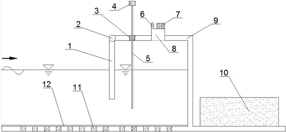
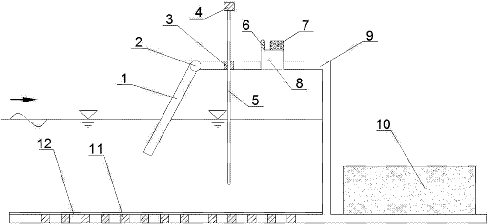
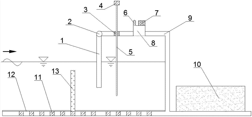
[0047] like figure 1 , Figure 7 As shown, a model test device for an oscillating water column wave energy conversion device, when no additional model is installed, consists of a front wall 1, a positioning screw 2, a rubber layer 3, an air pressure sensor 6, a wave height meter bracket 4, a wave height meter 5, Damping plate 7, air flow channel 8, model body 9, ballast block 10, card slot 11, water-proof bedding 12, shielding plate 18, and shielding plate interlayer 17; the interior of model body 9 is a hollow air chamber, and the two sides pass The visor 18 with the visor interlayer 17 is arranged to form a well-sealed air chamber structure. The wave-facing side of the front part of the model body 9 is connected to the front wall 1 through positioning screws 2, and a wave height meter 5 is...


PUM


Abstract

The invention discloses an onshore oscillating water column wave energy converter model testing device and a method, belonging to the hydraulic physical model testing field. In the oscillating water column wave energy converter model testing device, the front part of the device model body is connected with a front wall through a positioning screw. The upper part of the model body is sequentially provided with a wave height instrument, an air pressure sensor and a damping piece, wherein the air pressure sensor and the damping piece are connected through an air flow channel; the two sides of the model body are provided with shielding plates with shielding plate sandwiching layers to make the inner part of the model body form an air chamber structure with a good sealing effect. The lower part of the model body at the area opposite to the wave is provided with a ballast block; and the lower part of the model body at the area facing the wave is provided with an additional model through a clamping groove, and the clamping groove is provided with a water separating cover. The onshore oscillating water column wave energy converter model testing method comprises the following steps of: a testing preparation process, a testing process, an instrument sorting process and a data processing and analyzing process. The device of the invention is novel in design, simple in structure, good in integrity and applicable to wide working conditions. The testing device has the advantages of being high in test precision, convenient to operate in the testing process, high in testing efficiency, flexible in testing design and the like.

Description

technical field [0001] The invention relates to the field of hydraulic model tests of offshore engineering, in particular to a model test device and method for a shore-type oscillating water column wave energy conversion device. Background technique [0002] In nature, the ocean area accounts for about 71% of the total area of ​​the earth, which contains a huge wave energy reserve. The global exploitable annual wave energy reserve can reach 2TW, and wave power can be generated 90% of the time in a year. Wave energy is a high-quality renewable energy, and its scientific development is of great significance to alleviating the energy crisis and solving environmental pollution problems. [0003] In order to develop and utilize wave energy, many marine countries have actively carried out research on the development and utilization of wave energy, and have made great progress, and have explored and designed various types of wave energy conversion and utilization devices. The exis...

Claims


Application Information

Patent Timeline
IPC IPC(8): G01M10/00
CPCG01M10/00
Inventor 何方冷杰
Owner ZHEJIANG UNIV
Why Eureka
Try Eureka