Fiber fusion splicer and fiber tail end surface processing method

An optical fiber fusion splicer and optical fiber technology, applied in the direction of light guides, optics, optical components, etc., can solve the problems of small return loss, large equipment volume and weight, and increase the burden of carrying, so as to achieve return loss and insertion loss optimization, increase Volume and weight, saving manpower and financial resources

Pending Publication Date: 2017-12-15
深圳市中为光通信技术有限公司
View PDF6 Cites 5 Cited by
  • Summary
  • Abstract
  • Description
  • Claims
  • Application Information

AI Technical Summary

Problems solved by technology

[0008] To sum up, the existing optical fiber cold splicing technology has disadvantages: 1. If there is no condition to grind the end face of the optical fiber obtained by mechanical cutting, it will produce too large insertion loss and too small return loss after splicing, resulting in Light transmission loss is more serious
2. If there are construction requirements for optical fiber fusion splicing and optical fiber cold splicing at the same time, a lot of equipment needs to be carried, and the volume and weight of the equipment are large, which increases the burden of carrying, wastes manpower and increases costs

Method used


Image

  • Fiber fusion splicer and fiber tail end surface processing method
  • Fiber fusion splicer and fiber tail end surface processing method
  • Fiber fusion splicer and fiber tail end surface processing method

Examples


Embodiment Construction

[0028] In order to express the present invention more clearly, the present invention will be further described below in conjunction with the accompanying drawings.

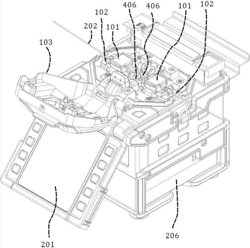
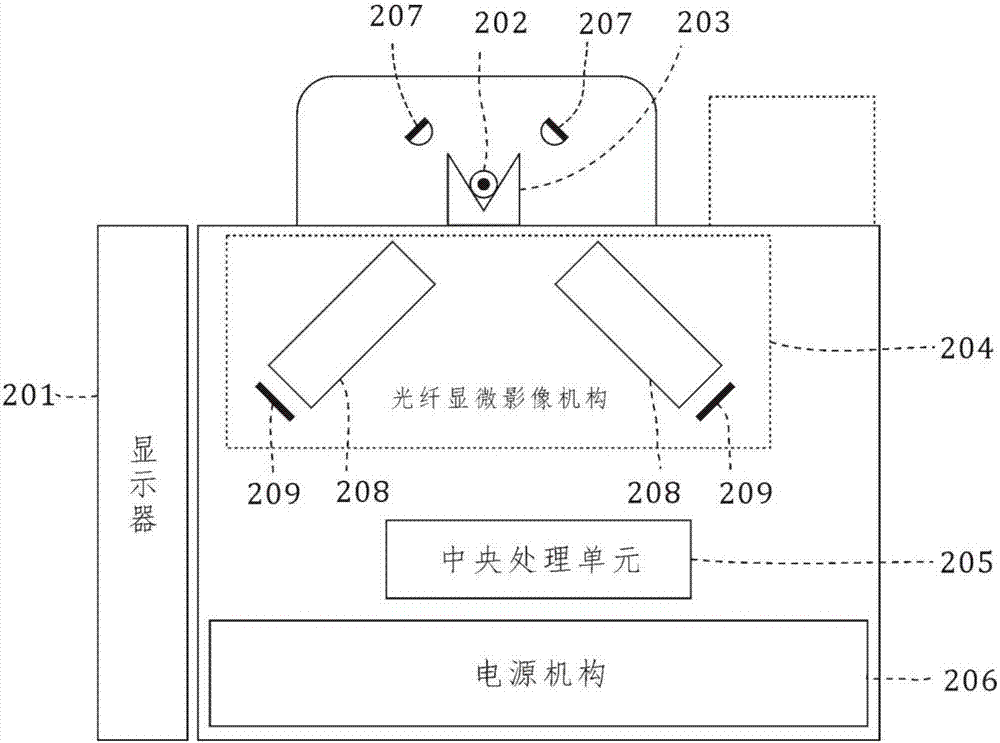
[0029] like Figure 1-2 As shown, an optical fiber fusion splicer includes a main body of the optical fiber fusion splicer; it also includes two optical fiber clamping mechanisms 101, two optical fiber propulsion mechanisms 102, an optical fiber microscopic imaging mechanism 204, a high-voltage discharge mechanism, a central processing unit 205, a power supply Mechanism 206; wherein two optical fiber clamping mechanisms 101 are symmetrically arranged, and the optical fiber advancing mechanism 102 is arranged at the lower end of the optical fiber clamping mechanism 101, and drives the end faces of the optical fibers 202 clamped by the optical fiber clamping mechanism 101 to approach each other; The above-mentioned high-voltage discharge mechanism is arranged between two optical fiber propulsion mechanisms 102 to ge...


PUM


Abstract

The invention discloses a fiber fusion splicer and a fiber tail end surface processing method. The method comprises main steps: the flatly-cut fiber tail end surface is pushed to the range of arc flame generated by an electrode rod through a pushing mechanism, the electrode rod then generates the arc flame lasting for a certain time duration to carry out smooth processing on the fiber tail end surface, the processing effects are monitored through a microscope and an image sensor, the fiber tail end surface processed by the method is used for cold welding, and the echo loss and the insertion loss are greatly optimized.

Description

technical field [0001] The invention relates to the field of an optical fiber fusion splicer, in particular to an optical fiber fusion splicer and a method for processing the end face of an optical fiber. Background technique [0002] In the construction of optical fiber communication, there are two commonly used splicing methods for optical fibers: hot splicing and cold splicing. [0003] The thermal splicing method is also called the fusion splicing method, which refers to the permanent splicing of two sections of optical fibers using an optical fiber fusion splicing machine as a special tool. [0004] The cold splicing method is to mechanically process the end faces of the two sections of optical fibers and then use a mechanical fixing device to fix the two sections of optical fibers in an aligned state. The fixing devices are divided into two types: pluggable connectors and fixed cold splices. kind. [0005] No matter which splicing method is used, the optical fiber wi...

Claims


Application Information

Patent Timeline
Patent Type & Authority Applications(China)
IPC IPC(8): G02B6/255G02B6/25
CPCG02B6/25G02B6/2551
Inventor 纪德海彭素娟
Owner 深圳市中为光通信技术有限公司
Why Eureka
Try Eureka