Supercharge Your Innovation With Domain-Expert AI Agents!

Permanent magnet speed regulator with constant air gap

A permanent magnet governor, air gap technology, applied in permanent magnet clutches/brakes, electrical components, electric brakes/clutches, etc., can solve the problem of poor torque transmission capacity, complex overall design of permanent magnet governors, and difficulty in assembly higher question

Active Publication Date: 2017-12-15
上海沃弗新能源科技有限公司
View PDF6 Cites 0 Cited by
  • Summary
  • Abstract
  • Description
  • Claims
  • Application Information

AI Technical Summary

Problems solved by technology

At present, most of the commonly used permanent magnet governors adjust the speed by adjusting the air gap. The power consumption of the magnetic circuit regulator is large, and there are disadvantages such as poor torque transmission capability, high assembly difficulty, and waste of a large amount of rare earth resources.
[0003] In order to solve this problem, the designer changes the effective coupling area between the permanent magnet rotor and the conductor rotor by changing the axial distance between the permanent magnet rotor and the conductor rotor of the permanent magnet governor, so as to achieve the effect of changing the torque at one time, but The current type of product has axial movement that needs to drive a lot of parts, which makes the overall design of the permanent magnet governor complex, or the adjustment device is connected externally, which makes it difficult to install and maintain the device in a specific place, and the addition of the adjustment device causes permanent magnets. The internal space of the governor is substantial, which is not conducive to the problem of heat dissipation

Method used


Image

  • Permanent magnet speed regulator with constant air gap
  • Permanent magnet speed regulator with constant air gap
  • Permanent magnet speed regulator with constant air gap

Examples


Embodiment Construction

[0023] The technical solutions of the present invention will be clearly and completely described below in conjunction with the embodiments. Apparently, the described embodiments are only some of the embodiments of the present invention, not all of them. Based on the embodiments of the present invention, all other embodiments obtained by persons of ordinary skill in the art without creative efforts fall within the protection scope of the present invention.

[0024] In describing the present invention, it is to be understood that the terms "opening", "upper", "lower", "thickness", "top", "middle", "length", "inner", "surrounding" etc. Indicating orientation or positional relationship is only for the convenience of describing the present invention and simplifying the description, and does not indicate or imply that the components or elements referred to must have a specific orientation, be constructed and operated in a specific orientation, and therefore cannot be construed as lim...


PUM


Abstract

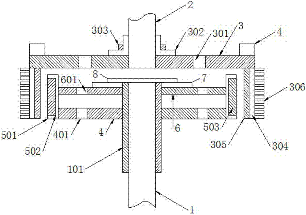
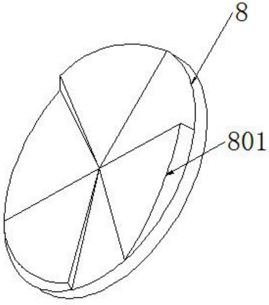
The invention discloses a permanent magnet speed regulator with a constant air gap, which comprises a driving shaft, a driven shaft and a regulating device, and is characterized in that the driving shaft is sleeved with a shaft sleeve, the shaft sleeve is sleeved with a permanent magnet rotary plate and a fixed rotary plate, a permanent magnet rotary cylinder is arranged in a sleeved manner by taking the periphery of the permanent magnet rotary plate and the fixed rotary plate as a fixed side, and the permanent magnet rotary cylinder is provided with a permanent magnet; one end of the driven shaft is sleeved with a conductor rotary plate, a regulating device is fixedly installed on a circumferential edge at one side of the conductor rotary plate, a fixed cylinder and a conductor cylinder are fixedly installed on a circumferential edge at the other side of the conductor rotary plate, the outer wall of the conductor cylinder and the inner wall of the fixed cylinder are arranged together, and the conductor cylinder is enabled to perform telescopic movements on the axial direction through the regulating device. The permanent magnet speed regulator changes the effective coupling area between the conductor cylinder and the permanent magnet through changing the position of the conductor cylinder so as to realize regulation for the rotating speed of a load. In addition, the permanent magnet speed regulator is enabled to generate a rotating air flow inside through changing the structure of a fastening disc so as to achieve a purpose of cooling.

Description

technical field [0001] The invention belongs to the field of speed regulating devices, and in particular relates to a permanent magnet speed regulating device with a constant air gap. Background technique [0002] The permanent magnet speed governor uses the magnetic coupling speed of the permanent magnet to realize the soft (magnetic) connection between the motor and the load without any harmonic generation affecting the power grid. , Inflammable and explosive, voltage instability and lightning and other harsh environments, greatly reducing mechanical vibration, widely used in electric power, steel, metallurgy, petrochemical, papermaking, municipal, ships, irrigation and mining industries. At present, most of the commonly used permanent magnet governors adjust the speed by adjusting the air gap. The magnetic circuit regulator consumes a lot of power, and has disadvantages such as poor torque transmission capability, high assembly difficulty, and waste of a large amount of r...

Claims


Application Information

Patent Timeline
Patent Type & Authority Applications(China)
IPC IPC(8): H02K49/10H02K5/20
CPCH02K5/20H02K49/106
Inventor 徐修昆
Owner 上海沃弗新能源科技有限公司
Features
  • R&D
  • Intellectual Property
  • Life Sciences
  • Materials
  • Tech Scout
  • Unparalleled Data Quality
  • Higher Quality Content
  • 60% Fewer Hallucinations
Learn More