Sludge scraping assembly

An assembly and mud scraper technology, applied in the field of sewage treatment, can solve problems such as potential safety hazards, waste of manpower, and influence on sedimentation effects, and achieve the effects of increasing resistance, avoiding agitation, and reducing costs

Pending Publication Date: 2017-12-19
河南中成环保科技股份有限公司
View PDF9 Cites 6 Cited by
  • Summary
  • Abstract
  • Description
  • Claims
  • Application Information

AI Technical Summary

Problems solved by technology

However, this technical solution has the following disadvantages: First, frequent lifting and lowering of the scraper device, when the scraper device enters and exits the sediment layer, the phenomenon of surface sludge re-suspension will occur. This phenomenon will become more and more severe, and the sludge in the sedimentation tank can be scraped off, but at the same time, the sedimentation effect is seriously affected; the second is that the underwater mud scraper device needs to be scraped several times during the mud scraping operation. It is inevitable that the connection between the wire rope and the wire rope connection ring will become loose or broken. However, since the underwater mud scraper device is generally below the horizontal plane, the field of vision is limited, and the connection between the wire rope and the wire rope connection ring is loose. It cannot be detected and repaired early. Timely maintenance, and after the wire rope and the connecting ring of the wire rope are broken, the underwater mud scraper device falls off in the water. For maintenance or replacement, the entire sedimentation tank needs to be emptied first, and then maintenance personnel go down to the bottom of the sedimentation tank for maintenance or replacement. Replacement will not only affect the efficiency of sewage treatment, but also waste manpower and material resources and have potential safety hazards; therefore, it is necessary to improve the existing technology to solve the above technical problems

Method used


Image

  • Sludge scraping assembly
  • Sludge scraping assembly
  • Sludge scraping assembly

Examples


Embodiment Construction

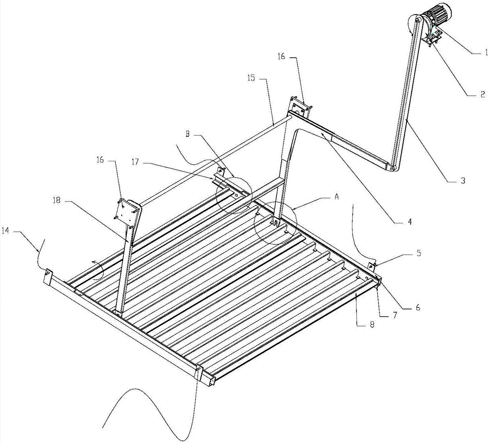
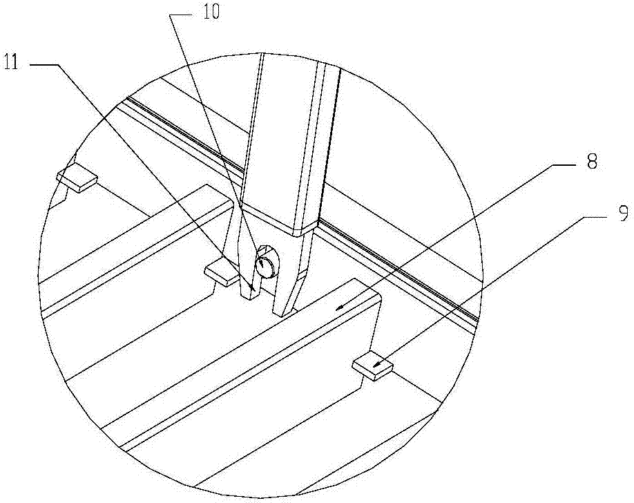
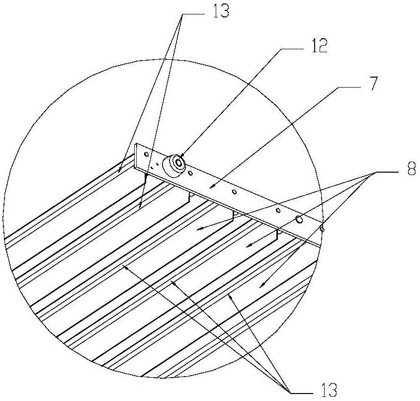
[0018] As shown in the figure: the mud scraping assembly in this embodiment includes a mud scraping assembly for scraping the sludge at the bottom of the sedimentation tank and a drive assembly for driving the mud scraping assembly to reciprocate back and forth; the mud scraping assembly includes a mud scraper 8 and the sliding plate 7 arranged at both ends of the mud scraper 8, the two ends of the mud scraper 8 are respectively connected to the sliding plate 8 with a single degree of freedom of rotation, and the sliding plate 7 is provided with a Carry out the spacer 9 of space-limiting during the state. The single-degree-of-freedom rotational connection can be realized as follows: the support shaft 13 is fixed on the mud scraper 8 , and a round hole for containing the support shaft 13 is provided on the sliding plate 7 . Of course, it can also be set in reverse, and a round hole is set on the mud scraper 8, and a support shaft 13 is set on the slide plate 7. When sliding pl...


PUM


Abstract

The invention discloses a sludge scraping assembly, and belongs to the technical field of sewage treatment. The sludge scraping assembly comprises a sludge scraping module used for scraping sludge at the bottom of a precipitation tank and a driving module for driving the sludge scraping module to reciprocate back and forth; the sludge scraping module comprises sludge scraping plates and slide plates arranged at two ends of the sludge scraping plates, two ends of the sludge scraping plates are respectively connected to the slide plates in a single-degree-of-freedom rotating manner, the slide plates are provided with spacing members for spacing the sludge scraping plates being in a sludge scraping state, and the driving module comprises a connecting lever and a driving mechanism for driving the connecting lever to swing back and forth; and the lower end of the connecting lever is hinged to one of the slide plates in a sliding manner. The sludge scraping module always reciprocate on the horizontal plane determined by the bottom of the precipitation tank without up-and-down elevation motion, so the strong stirring of the sludge scraping module to precipitated sludge is effectively avoided, and natural precipitation is facilitated.

Description

technical field [0001] The invention relates to a mud scraping assembly, which belongs to the technical field of sewage treatment. Background technique [0002] The underwater mud scraper device is a common equipment for sewage treatment, and it is used for mud scraping in the sedimentation tank. During operation, the underwater mud scraper device is close to the bottom of the tank and runs from one end of the sedimentation tank to the sludge discharge tank at the other end to discharge the sludge. Put the underwater mud scraper device down to a suitable position at the starting end of the operation of the lower mud scraper device to complete a working stroke. However, this technical solution has the following disadvantages: First, frequent lifting and lowering of the scraper device, when the scraper device enters and exits the sediment layer, the surface sludge will be suspended again. Increasing this phenomenon will become more and more severe, and it can scrape off the ...

Claims


Application Information

Patent Timeline
Patent Type & Authority Applications(China)
IPC IPC(8): B01D21/18B01D21/20
CPCB01D21/183B01D21/20
Inventor 王杨许静
Owner 河南中成环保科技股份有限公司
Why Eureka
Try Eureka