Gear trough impurity removal device
An impurity and tooth slot technology, applied in the field of gear cleaning devices, can solve the problems of low efficiency of manual cleaning of gears, bruised gear meshing teeth, etc., and achieve the effects of improving gear cleaning efficiency, avoiding bruising and reducing cleaning time.
- Summary
- Abstract
- Description
- Claims
- Application Information
AI Technical Summary
Problems solved by technology
Method used
Image

Examples
Embodiment 1
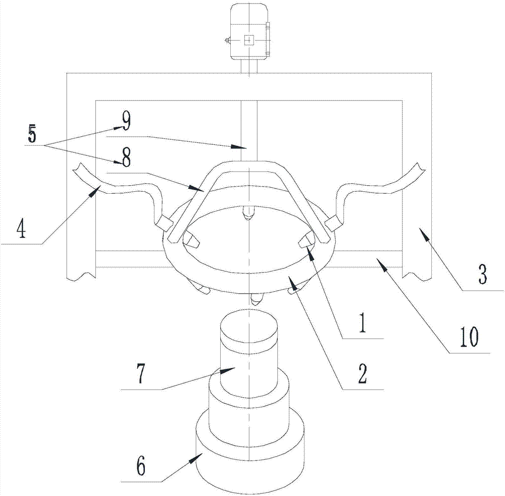
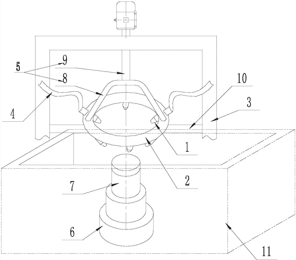
[0035] Such as Figure 1-Figure 2 As shown, a device for removing alveolar impurities of the present invention includes a storage tank filled with gear cleaning agent, a nozzle 1, a fixed ring 2 and a support frame 3. There are several nozzles 1, and they are all installed on the fixed ring 2 , and the direction of the nozzle 1 points to a point on the axis of the fixed ring 2, and the storage tank sends the gear cleaning agent into the nozzle 1 through the hydraulic pump and the pipeline 4;
[0036] The fixing ring 2 is connected to the supporting frame 3 through the connecting component 5, and the motor drives the connecting component 5 to rotate, and drives the fixing ring 2 to rotate around its own axis.
[0037] The gear cleaning agent can use water-based cleaning agent, gasoline, kerosene, alcohol and other solvents.
[0038] Place the gear on the side of the fixed ring 2 away from the motor, and the gear is coaxial with the fixed ring 2, then start the hydraulic pump a...
Embodiment 2
[0040] The present invention is based on embodiment 1, and the present invention is further described.
[0041] Such as Figure 1-Figure 2 As shown, a device for removing alveolar impurities in the present invention is provided with a telescopic device 6 on the end of the fixed ring 2 away from the motor, the telescopic device 6 is coaxial with the fixed ring 2, and the telescopic end of the telescopic device 6 faces the fixed ring 2;
[0042] A limit shaft 7 is arranged at the telescopic end of the telescopic device, the limit shaft 7 is coaxial with the fixed ring 2, and the cross-sectional area of the limit shaft 7 is smaller than that of the telescopic end. When the axial length of the gear is relatively large, it is necessary to move the gear or the nozzle 1 along the axial direction of the gear so that the nozzle 1 can clean the entire gear.
[0043] Set the gear on the limit shaft 7. During cleaning, the nozzle 1 sprays the cleaning solution onto the gear at the en...
Embodiment 3
[0046] The present invention is based on embodiment 1, and the present invention is further described.
[0047] Such as Figure 1-Figure 2 As shown, the present invention is a device for removing alveolar impurities. The point of the nozzle 1 located on the axis of the fixed ring 2 does not coincide with the orthographic projection of the fixed ring 2 falling on the plane where the axis is located, and the direction of the nozzle 1 A point on the axis of the fixed ring 2 is located on the side of the fixed ring 2 away from the motor.
[0048] When the point of the nozzle 1 on the axis of the fixed ring 2 coincides with the orthographic projection of the fixed ring 2 falling on the plane where the axis is located, the cleaning agent sprayed by the nozzle 1 coincides with the gear radial direction, and the sprayed cleaning agent at this time After the agent contacts the gear, it will sputter to both ends of the gear, causing some iron filings to splash on the cleaned surface, i...
PUM
 Abstract
Description
Claims
Application Information
 - R&D
- Intellectual Property
- Life Sciences
- Materials
- Tech Scout
- Unparalleled Data Quality
- Higher Quality Content
- 60% Fewer Hallucinations
Browse by: Latest US Patents, China's latest patents, Technical Efficacy Thesaurus, Application Domain, Technology Topic, Popular Technical Reports.
© 2025 PatSnap. All rights reserved.Legal|Privacy policy|Modern Slavery Act Transparency Statement|Sitemap|About US| Contact US: help@patsnap.com