Centrifugal farm-chemical spraying multi-rotor unmanned aerial vehicle
A multi-rotor unmanned aerial vehicle, centrifugal technology, applied in the direction of rotorcraft, unmanned aerial vehicle, motor vehicle, etc. Actionable effect
- Summary
- Abstract
- Description
- Claims
- Application Information
AI Technical Summary
Problems solved by technology
Method used
Image
Examples
Embodiment 1
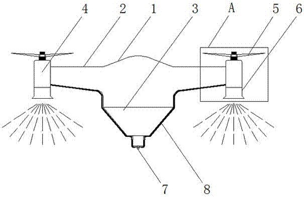
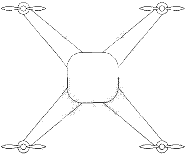
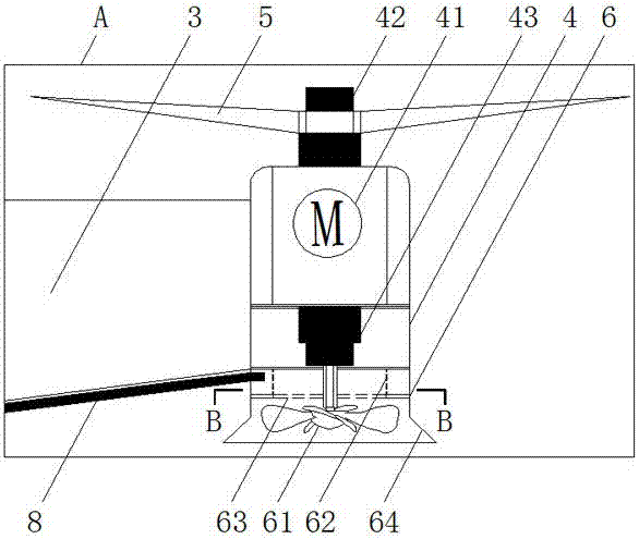
[0028] combined with Figure 1-3 As shown, a centrifugal drug spraying multi-rotor UAV includes a multi-rotor UAV fuselage 1, a machine arm 2 and a motor base 4 fixedly connected to the machine arm 2, and the bottom of the motor base 4 is detachable Fixedly connected with sprinkler system 6, as attached image 3 As shown, the nozzle system 6 includes a cylindrical housing 64 with an opening on the side wall and an impeller 61 for atomizing medicine, and a double motor with an upper output end 42 and a lower output end 43 is installed in the motor base 4. Head motor 41, rotor 5 for providing lift is installed on the upper output end 42, and the lower output end 43 is drivingly connected with the impeller 61; a storage bin 3 with a booster pump is installed under the fuselage 1 , the top of the storage bin is provided with a drug inlet, and the bottom is provided with a drug outlet, and a delivery pipe 8 for communication is arranged between the drug outlet and the opening of t...
Embodiment 2
[0036] On the basis of Example 1, in conjunction with the attached Figure 4 , 5 As shown, further, a screen 63 with a central hole is installed inside the housing 64, the edge of the screen is a solid ring, and a porous screen wall 62 is fixedly arranged on the solid ring, and the porous screen The aperture of the wall 62 is larger than the aperture of said screen 63 .
[0037] An annular cavity is formed between the porous sieve wall 62 and the housing 64 , the pressurized pump in the storage bin 3 works, the liquid medicine is pumped to the nozzle system 6 through the delivery pipe 8 , and the liquid medicine enters the housing 64 and the annular cavity between the porous sieve wall 62, and then seep out evenly through the pores around the porous sieve wall 62, because the aperture of the porous sieve wall 62 is greater than the aperture of the screen 63, The water inflow of the net 63 is greater than the water outflow, and there is a certain depth of liquid medicine on t...
Embodiment 3
[0039] On the basis of embodiment 1 or 2, in conjunction with the attached figure 1 , 6 , 7, the storage bin 3 is an inverted cone or a regular polygonal pyramid, and the lowermost end of the storage bin 3 is provided with a drug outlet, and a spherical branch 7 is installed on the drug outlet. Brancher 7 includes a hollow spherical cavity, a main pipe connected to the drug outlet, and a branch pipe connected to delivery pipe 8 .
[0040] By setting the storage bin 3 as an inverted cone or a regular polygonal pyramid, the center of gravity of the storage bin 3 is always located at the center of the drone fuselage regardless of the amount of liquid medicine in stock, so as to avoid unstable center of gravity of the drone , at the same time, a drug outlet is set at the lowermost end of the storage bin 3, which is beneficial to the output of liquid medicine, and a spherical branch device 7 is installed at the drug outlet, and the water pressure at each branch pipe of the spheric...
PUM
 Abstract
Description
Claims
Application Information
 - R&D
- Intellectual Property
- Life Sciences
- Materials
- Tech Scout
- Unparalleled Data Quality
- Higher Quality Content
- 60% Fewer Hallucinations
Browse by: Latest US Patents, China's latest patents, Technical Efficacy Thesaurus, Application Domain, Technology Topic, Popular Technical Reports.
© 2025 PatSnap. All rights reserved.Legal|Privacy policy|Modern Slavery Act Transparency Statement|Sitemap|About US| Contact US: help@patsnap.com


