
Reflection-type ultrasonic shot-peening strengthening device for inner hole surface

An ultrasonic shot peening and strengthening device technology, which is applied in the field of parts surface strengthening equipment, can solve the problems of large environmental pollution, high energy consumption, and large shot peening consumption, and achieve the effects of low environmental pollution, low energy consumption, and space saving

Inactive Publication Date: 2017-12-19
SHENYANG AEROSPACE UNIVERSITY
View PDF5 Cites 8 Cited by
  • Summary
  • Abstract
  • Description
  • Claims
  • Application Information

AI Technical Summary

Problems solved by technology

[0007] The purpose of the present invention is to provide a reflective ultrasonic shot peening strengthening device on the surface of the inner hole, which is used to solve the problem of large amount of shot blasting, large environmental pollution, high energy consumption, space occupation and damage to the inner hole of the parts in the existing shot blasting machine. The problem of poor reinforcement effect

Method used


Image

  • Reflection-type ultrasonic shot-peening strengthening device for inner hole surface
  • Reflection-type ultrasonic shot-peening strengthening device for inner hole surface
  • Reflection-type ultrasonic shot-peening strengthening device for inner hole surface

Examples


Embodiment 1

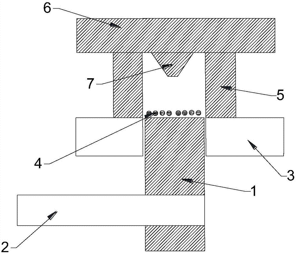
[0020] Such as figure 1 As shown, the ultrasonic shot peening device on the surface of the inner hole includes a cover plate 6, a workbench 3 and an ultrasonic vibrating head 1. The part 5 to be processed has a through hole, and the working table 3 is provided with a positioning hole. The ultrasonic vibrating head 1 consists of The mechanical arm 2 is clamped and installed in the positioning hole. The mechanical arm 2 clamps the ultrasonic vibration head 1 and can move up and down along the axis of the positioning hole. By controlling the mechanical arm 2, the depth of the ultrasonic vibration head 1 entering the through hole can be changed. The ultrasonic vibration head 1 is connected to the transducer through the horn, and the transducer is electrically connected to the ultrasonic generator. After the ultrasonic generator is powered on, a high-frequency electrical oscillation signal of 15-40KHz is sent to the transducer, and the transducer will receive The received electric ...

Embodiment 2

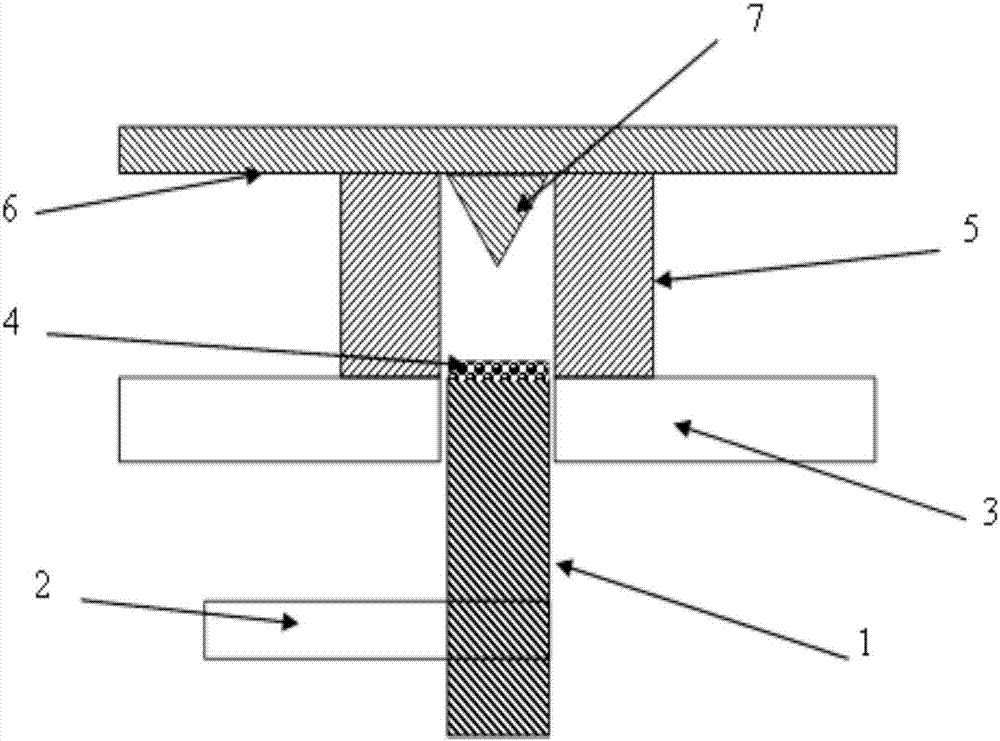
[0025] Such as figure 2 As shown, the ultrasonic shot peening device on the surface of the inner hole includes a cover plate 6, a workbench 3 and an ultrasonic vibration head 1. The difference between this embodiment and Embodiment 1 is that in this embodiment, the convex part 7 is in this embodiment The middle is an inverted cone, and the taper of the cone is preferably 45°. Compared with the convex part 7 of the inverted frustum of the conical body in Example 1, the convex part 7 of this embodiment can reflect more shot blasting 4 and hit the hole wall of the through hole, which has a better strengthening effect on the hole wall of the through hole. In Example 1.


PUM

PropertyMeasurementUnit
diameteraaaaaaaaaa

Abstract

The invention relates to a reflection-type ultrasonic shot-peening strengthening device for an inner hole surface. The reflection-type ultrasonic shot-peening strengthening device for the inner hole surface comprises a cover plate, a workbench and an ultrasonic vibrating head. The workbench is provided with a positioning hole, and a to-be-processed part with a through hole is fixed to the workbench through a fixing part. The ultrasonic vibrating head is movably installed in the positioning hole. The through hole of the to-be-processed part corresponds to the positioning hole, so that the ultrasonic vibrating head penetrates through the positioning hole and then enters the through hole via a lower end opening of the through hole. The cover plate is fixed above the to-be-processed part. An upper end opening of the through hole can be blocked through the cover plate so that a closed cavity can be formed. A plurality of shot blasting bodies are placed in the cavity. A protruding part is arranged on the lower surface of the cover plate and further protrudes downwards to enter the through hole. The ultrasonic shot-peening strengthening device provided by the invention has the advantages that energy consumption is small, space can be saved, environmental pollution is low, the using quantity of the shot blasting bodies is small and the strengthening effect on the inner hole surface of the part is good.

Description

technical field [0001] The invention relates to the technical field of parts surface strengthening equipment, in particular to a reflection type ultrasonic shot peening strengthening device for the surface of an inner hole. Background technique [0002] Disc and shaft parts of aeroengines include: turbine discs, compressor blade discs, bearings, gear discs, etc., which usually need to withstand high cycle fatigue loads during engine operation. In order to improve the fatigue strength of such parts, the surface strengthening process is generally used for strengthening treatment. [0003] Shot peening is the most common surface strengthening process in this field. Traditional shot peening equipment mainly includes two types of pneumatic shot blasting machine and centrifugal shot blasting machine. The pneumatic shot blasting machine is supplied with compressed air by an air compressor. When the air passes through the spray gun, the negative pressure will cause the shot peening...

Claims


Application Information

Patent Timeline
Patent Type & Authority Applications(China)
IPC IPC(8): C21D7/06
CPCC21D7/06
Inventor 蔡晋刘建邦
Owner SHENYANG AEROSPACE UNIVERSITY
Learn More