
Ground compaction machine, in particular rubber-tired roller, having a wheel cover, and wheel cover

A technology of rubber tires and compactors, which is applied in the field of rubber tire road rollers, can solve the problems of enlarged overall size of ground compactors, complex and unfavorable precise steering of ground compactors, etc., and achieve simplified operation, improved heat insulation, handling and transportation easy effect

Active Publication Date: 2017-12-19
BOMAG
View PDF6 Cites 2 Cited by
  • Summary
  • Abstract
  • Description
  • Claims
  • Application Information

AI Technical Summary

Problems solved by technology

Rather protruding wheel housings would lead to an increase in the overall size of the ground compactor, which would be disadvantageous for maneuvering the ground compactor and its transport (e.g. on a truck)
In addition, accurate steering of the ground compactor is complicated by the operator, and the wheel rim of the rubber-tyred roller is not visible to the operator due to the presence of protruding wheel housings

Method used


Image

  • Ground compaction machine, in particular rubber-tired roller, having a wheel cover, and wheel cover
  • Ground compaction machine, in particular rubber-tired roller, having a wheel cover, and wheel cover
  • Ground compaction machine, in particular rubber-tired roller, having a wheel cover, and wheel cover

Examples


Embodiment Construction

[0041] Similar or equivalent parts are indicated by the same reference numerals throughout the drawings. Repeated components are not necessarily shown separately in each figure.

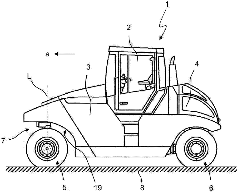
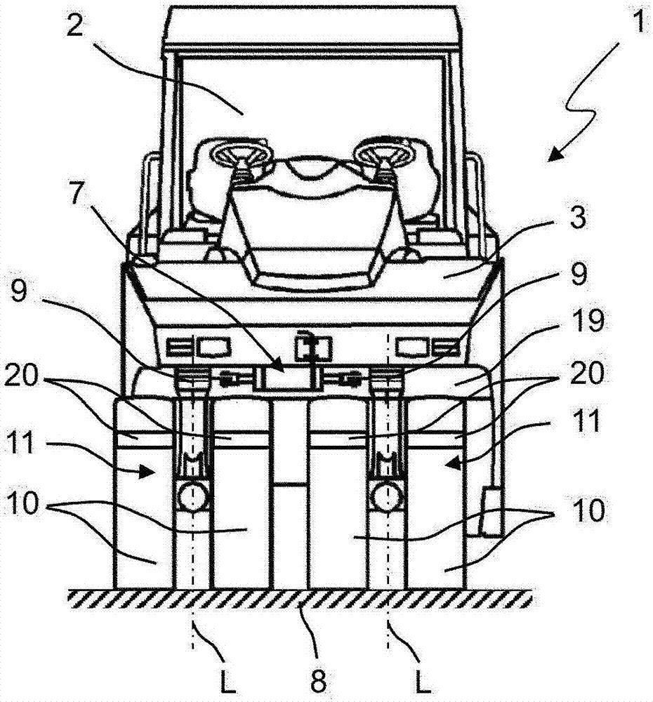
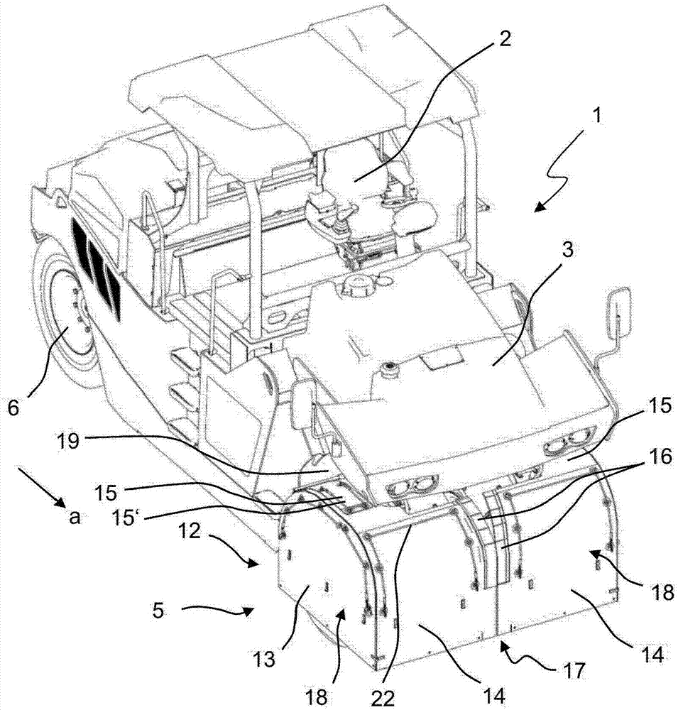
[0042] figure 1 with figure 2 A universal ground compactor 1 with an operator's platform 2 and a frame 3 is shown. Furthermore, the ground compactor 1 comprises a chassis driven by a propulsion unit 4 , mostly a diesel combustion engine, which, as shown in the exemplary embodiment, comprises a front chassis section 5 and a rear chassis section 6 . During the working operation of the ground compactor 1 , it moves along the working direction a over the ground 8 and compacts it. figure 2 Details of the front chassis section 5 are shown. The front chassis part 5 comprises a steering device 7 and two chassis units 11 . The chassis units 11 each comprise two wheels 10 and a steerable support column 9 . The undercarriage units 11 are each designed to be rotatable about two vertical steering axes L e...


PUM


Abstract

Ground compaction machine, which can be a rubber-tired roller, operable to compact ground in a working direction is presented, along with a wheel cover for the same. The machine can have a machine frame and a chassis supporting the machine frame. The machine frame having a front chassis portion and a rear chassis portion. At least one of the front chassis portion or rear chassis portion has at least two chassis units, each chassis unit being rotatable about a distinct steering axis. Each chassis unit having at least one wheel, and a wheel cover, which is formed for thermal insulation of the chassis units from the external surroundings, the wheel cover comprising at least two wheel cover units, and a wheel cover unit being arranged on each chassis unit, which is configured to be rotatable about the respective distinct steering axis together with the respective chassis unit.

Description

technical field [0001] The invention relates to a ground compactor, in particular a rubber-tyred road roller, for compacting the ground along a working direction. Furthermore, the invention relates to a wheel cover for use on a ground compactor. Background technique [0002] Typical ground compactors are used in such road and path construction, for example, where the ground compactor will compact and stabilize the ground before a base layer such as an asphalt cap is laid. Likewise, a base layer laid on compacted ground will be compacted and thus consolidated with a common ground compactor. Various ground compactors are known, such as road rollers, tandem rollers or rubber-tyred rollers, which are used for different applications. A general purpose ground compactor includes a frame and a chassis supporting the frame, the chassis including a front chassis section and a rear chassis section. These chassis parts can be, for example, the front and rear drums of a tandem roller....

Claims


Application Information

Patent Timeline
IPC IPC(8): E01C19/26
CPCE01C19/27E01C19/26E01C19/238E02D3/026B60R19/00B60R2019/002
Inventor C·贝格E-J·艾诺尔夫T·施恩贝格
Owner BOMAG
Learn More