Wireless laser communication device
A communication device and wireless laser technology, applied in the field of communication, can solve the problems of poor anti-interference, small channel bandwidth, low data transmission rate, etc., and achieve the effects of improving network coverage, high confidentiality and anti-interference.
- Summary
- Abstract
- Description
- Claims
- Application Information
AI Technical Summary
Problems solved by technology
Method used
Image

Examples
Embodiment Construction
[0019] The specific embodiments of the present invention will be described in detail below in conjunction with the accompanying drawings.
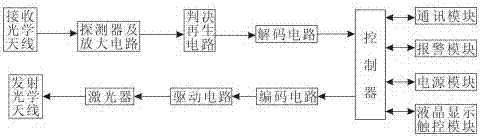
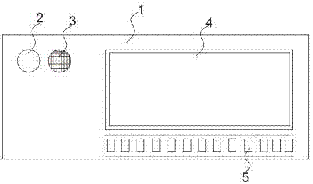
[0020] In one embodiment of the present invention, as Figure 1~4 As shown, a wireless laser communication device is provided, including a housing 1, a laser transceiver device disposed inside the housing 1, and a wireless optical router connected to the laser transceiver end, and a liquid crystal screen 4 and a keyboard 5 are arranged on one side of the housing 1, The other side is provided with a laser array 7; the laser transceiver device includes a controller and a laser input module and a laser output module connected to the controller, and the laser input module includes a receiving optical element 8, a detector and an amplifier circuit, and a judgment regeneration circuit connected in sequence And the decoding circuit, the laser output module includes an encoding circuit, a drive circuit, a laser and an emitting optical element 9 co...
PUM
 Abstract
Description
Claims
Application Information
 - Generate Ideas
- Intellectual Property
- Life Sciences
- Materials
- Tech Scout
- Unparalleled Data Quality
- Higher Quality Content
- 60% Fewer Hallucinations
Browse by: Latest US Patents, China's latest patents, Technical Efficacy Thesaurus, Application Domain, Technology Topic, Popular Technical Reports.
© 2025 PatSnap. All rights reserved.Legal|Privacy policy|Modern Slavery Act Transparency Statement|Sitemap|About US| Contact US: help@patsnap.com