Joint torque measuring system for injured finger rehabilitation
A joint torque and measurement system technology, applied in control/adjustment systems, torque measurement, measurement devices, etc., can solve problems such as lack of sensing function and inability to measure the interaction force between finger joints and exoskeletons, and achieve low prices. , the effect of injury prevention, high sensitivity and measurement accuracy
- Summary
- Abstract
- Description
- Claims
- Application Information
AI Technical Summary
Problems solved by technology
Method used
Image
Examples
specific Embodiment approach 1
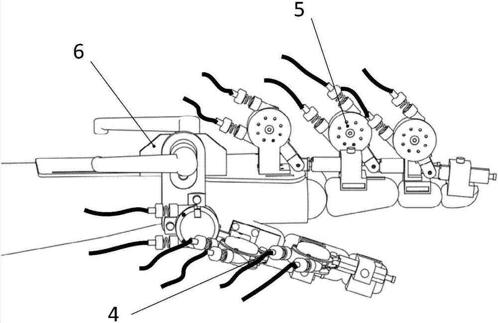
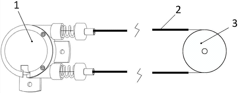
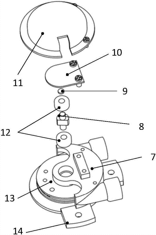
[0024] Specific implementation mode one: as Figure 1-7 As shown, the joint torque measurement system used for trauma finger rehabilitation in this embodiment includes several joint torque measurement units, each joint torque measurement unit exoskeleton joint unit 1, Bowden wire 2, motor output terminal wire wheel 3 and two Elastic element; the motor output wire wheel 3 is installed on the output shaft of the drive motor, the exoskeleton joint unit 1 includes a joint seat 14, a joint wire wheel 13, a joint angle sensor 10, two bearings 12, a D-shaped shaft 8, and a wire wheel frame 7. The magnetic steel 9 and the joint seat end cover 11; the D-shaped shaft 8 is mounted on the joint wire wheel 13, and the two ends of the D-shaped shaft 8 are installed on the wire wheel frame 7 through two bearings 12, and the joint angle sensor 10 is passed through the screw Fixed on the upper end surface of the line wheel frame 7, the magnetic steel 9 is pasted on the upper end surface of the...
specific Embodiment approach 2
[0076] Specific implementation mode two: as image 3 As shown, the joint angle sensor 10 of this embodiment is a non-contact position sensor based on the Hall principle. With this design, when measuring the angular position, the chip is located under the magnetic steel 9 fixed on the rotating shaft, and the magnetic steel 9 is radially magnetized, so when the D-shaped shaft 8 rotates, the magnetic field passing through the Hall chip also rotates. Other components and connections are the same as those in the first embodiment.
specific Embodiment approach 3
[0077] Specific implementation mode three: as image 3 As shown, the joint seat end cover 11 of this embodiment is fixed on the upper end surface of the wire wheel frame 7 by two screws. So designed, easy to disassemble. Other compositions and connections are the same as those in Embodiment 1 or 2.
PUM
 Abstract
Description
Claims
Application Information
 - R&D
- Intellectual Property
- Life Sciences
- Materials
- Tech Scout
- Unparalleled Data Quality
- Higher Quality Content
- 60% Fewer Hallucinations
Browse by: Latest US Patents, China's latest patents, Technical Efficacy Thesaurus, Application Domain, Technology Topic, Popular Technical Reports.
© 2025 PatSnap. All rights reserved.Legal|Privacy policy|Modern Slavery Act Transparency Statement|Sitemap|About US| Contact US: help@patsnap.com


