Direct heat circulation type waste heat recycling system

A waste heat recovery system and waste heat recovery technology, applied in heat exchangers, heat exchanger types, indirect heat exchangers, etc., can solve the problems of recovery efficiency and short service life, and achieve low mixing rate, low pressure loss, Low maintenance effect

Inactive Publication Date: 2017-12-22
中山市睿丰智能科技有限公司
View PDF0 Cites 1 Cited by
  • Summary
  • Abstract
  • Description
  • Claims
  • Application Information

AI Technical Summary

Problems solved by technology

[0002] Waste heat recovery systems in the prior art generally have defects such as recovery efficiency and short service life. In order to overcome these defects, it is necessary to develop a new type of waste heat recovery system

Method used


Image

  • Direct heat circulation type waste heat recycling system

Examples


Embodiment Construction

[0013] The present invention will be further described below with reference to the accompanying drawings and embodiments, and the mode of the present invention includes but not limited to the following embodiments.

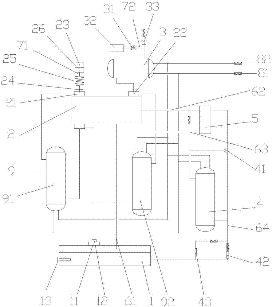
[0014] The purpose of this embodiment is to provide a direct heat circulation waste heat recovery system, such as figure 1 As shown, the waste heat recovery system includes an oil tank 1, a waste heat recovery device 2, an intercooler 9, an aftercooler 3, an oil cooler 4 and an oil filter 5; the top of the oil tank 1 and the bottom of the waste heat recovery device 2 pass through a first The oil pipe 61 is connected to the pipeline, and the top of the oil tank is also provided with a filter 11, and an oil exhaust fan 12 is connected above the filter, and an oil heater 13 is arranged on one side of the oil tank; the side of the waste heat recovery device 2 is connected to the oil filter 5 One side is connected with the second oil pipe 62, and the second oil pipe 62...


PUM


Abstract

The invention discloses a direct heat circulation waste heat recovery system, which comprises an oil tank, a waste heat recoverer, an intercooler, an aftercooler, an oil cooler and an oil filter, and the oil tank is located between the waste heat recoverer and the oil cooler. They are all connected by oil pipes, and the waste heat recovery device, the intercooler and the aftercooler are all connected by air pipes, and the waste heat recovery device and the aftercooler are also equipped with air pipes communicating with the atmosphere, and A muffler is arranged on the air pipeline, and the intercooler, the aftercooler and the oil cooler are all connected to the water inlet main pipe and the water outlet main pipe. The direct heat circulation waste heat recovery system has the advantages of low mixing ratio, low pressure loss, zero overflow, low circulation speed, long service life and low maintenance.

Description

technical field [0001] The invention relates to a waste heat recovery system, in particular to a direct heat circulation waste heat recovery system. Background technique [0002] Waste heat recovery systems in the prior art generally have defects such as recovery efficiency and short service life. In order to overcome these defects, it is necessary to develop a new type of waste heat recovery system. Contents of the invention [0003] The purpose of the present invention is to provide a direct heat circulation waste heat recovery system with the advantages of low mixing rate, low pressure loss, zero overflow, low circulation speed, long service life and low maintenance. [0004] To achieve the above object, the technical scheme adopted in the present invention is as follows: [0005] A direct heat circulation waste heat recovery system, including an oil tank, a waste heat recovery device, an intercooler, an aftercooler, an oil cooler, and an oil filter; the top of the oil...

Claims


Application Information

Patent Timeline
Patent Type & Authority Applications(China)
IPC IPC(8): F28D21/00
CPCF28D21/0001
Inventor 朱燕雅
Owner 中山市睿丰智能科技有限公司
Why Eureka
Try Eureka