Flue gas purification treatment process for biomass power plant

A flue gas purification and treatment process technology, applied in the direction of gas treatment, climate change adaptation, climate sustainability, etc., can solve the problems of catalyst activity loss, equipment corrosion and dust deposition, high viscosity and strength, etc., to reduce tar adhesion, The effect of low maintenance cost and large contact area

Inactive Publication Date: 2018-12-14
杭州玺富环保科技有限公司
View PDF7 Cites 0 Cited by
  • Summary
  • Abstract
  • Description
  • Claims
  • Application Information

AI Technical Summary

Problems solved by technology

Biomass has a smooth surface and less porosity than the ash deposits during coal combustion, so the viscosity and strength are relatively high, so the ash deposits produced by biomass combustion are more difficult to remove, and then biomass combustion ash appears Corrosion and dust accumulation problems caused by equipment
On the other hand, the flue gas treatment equipment of biomass power plants is generally traditional honeycomb or plate SCR, which cannot avoid contact with dust containing alkaline metals (Na, K, etc.) Denitrification efficiency, while the catalyst denitrification temperature needs to be between 280-350 degrees Celsius. Generally, the cloth bag cannot withstand this high temperature, so it is impossible to treat the dust at the front end of the SCR. If the cloth bag is used to remove the dust at the front end, the temperature must be lowered to below 250 degrees Celsius to remove the dust. Then heat up to the denitrification temperature (280-350 degrees Celsius), wasting energy

Method used


Image

  • Flue gas purification treatment process for biomass power plant

Examples


Embodiment Construction

[0015] The technical scheme of the present invention will be further described below in conjunction with the accompanying drawings of the description:

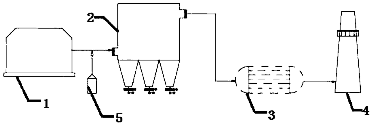
[0016] Such as figure 1 As shown, the biomass power plant flue gas purification treatment process includes the following steps:

[0017] The first step: fully mix the flue gas produced by burning biomass from the biomass boiler 1 of the biomass power plant with ammonia water 5, and then obtain the mixed high-temperature flue gas;

[0018] Step 2: Pass the mixed high-temperature flue gas through the catalytic ceramic fiber filter tube integrated denitrification and dust removal chamber 2 for denitrification reaction and dust removal treatment, so as to remove dust and nitrogen oxides in the mixed flue gas, and then obtain the treated flue gas smoke;

[0019] The third step: the treated flue gas is recovered through the waste heat boiler 3 to obtain purified flue gas after cooling;

[0020] Step 4: Discharge the purified flue...


PUM


Abstract

The invention discloses a flue gas purification treatment process for a biomass power plant. The flue gas purification treatment process comprises the following steps: step one: flue gas generated from combusted biomass in a biomass boiler of a biomass power plant is fully mixed with ammonia water, and then mixed high-temperature flue gas is obtained; step two, the mixed high-temperature flue gasis subjected to a denitration reaction and dust removal treatment through a catalyst ceramic fiber filter pipe integrated denitration and dust removal chamber, so that dust and nitrogen oxides in themixed flue gas are removed, and then treated flue gas is obtained; step three, heat energy recovery is carried out on the treated flue gas through a waste heat boiler, and cooled purified flue gas isobtained; and step four, the purified smoke is discharged into the air through a chimney. According to the flue gas purification treatment process, dust and nitrogen oxides in flue gas can be effectively removed, the waste heat recovery benefit is high, and the resource utilization rate is high.

Description

technical field [0001] The invention relates to a flue gas purification treatment process of a biomass power plant. Background technique [0002] On the one hand, the ash produced by the fuel combustion of biomass power plants mainly includes quartz and simple inorganic substances, such as Fe, Ca, Mg, Na and S, phosphate and Cl, etc., and the melting temperature is relatively low. , with a high tendency to slagging, scaling and corrosion. Biomass has a smooth surface and less porosity than the ash deposits during coal combustion, so the viscosity and strength are relatively high, so the ash deposits produced by biomass combustion are more difficult to remove, and then biomass combustion ash appears The equipment corrosion and dust accumulation problems caused by it. On the other hand, the flue gas treatment equipment of biomass power plants is generally traditional honeycomb or plate SCR, which cannot avoid contact with dust containing alkaline metals (Na, K, etc.) Denitr...

Claims


Application Information

Patent Timeline
IPC IPC(8): B01D53/75B01D53/56B01D46/24
CPCB01D46/2411B01D53/56B01D53/75B01D2258/0283Y02A50/2351
Inventor 沈毅陈俊宇曹熠陈俊豪叶芮榄胡波
Owner 杭州玺富环保科技有限公司
Why Eureka
Try Eureka