A piezoelectric ceramic driving device and driving method

A piezoelectric ceramic drive, piezoelectric ceramic technology, applied in piezoelectric effect/electrostrictive or magnetostrictive motors, generators/motors, electrical components, etc., can solve the problem of large thermal power consumption, small output current, Problems such as low output voltage to achieve the effect of reducing thermal power consumption and improving the increase

Inactive Publication Date: 2019-06-21
TIANJIN UNIV
View PDF5 Cites 0 Cited by
  • Summary
  • Abstract
  • Description
  • Claims
  • Application Information

AI Technical Summary

Problems solved by technology

[0003] Aiming at the defects of low output voltage, small output current and large thermal power consumption of the piezoelectric ceramic driving device in the prior art, the present invention provides a piezoelectric ceramic driving device capable of outputting high voltage, high current and good heat dissipation performance

Method used


Image

  • A piezoelectric ceramic driving device and driving method
  • A piezoelectric ceramic driving device and driving method
  • A piezoelectric ceramic driving device and driving method

Examples


Embodiment Construction

[0014] The technical solution of the present invention will be further described in detail below in conjunction with the accompanying drawings and specific embodiments. The specific embodiments described are only for explaining the present invention and are not intended to limit the present invention.

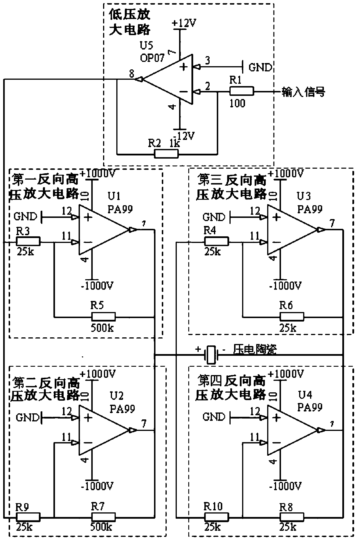
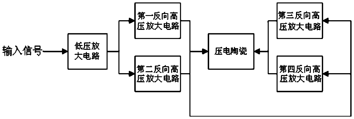
[0015] Such as figure 1 As shown, a piezoelectric ceramic drive device proposed by the present invention includes a low voltage amplifier circuit and four reverse high voltage amplifier circuits. The four reverse high voltage amplifier circuits are respectively marked as the first reverse high voltage amplifier circuit and the second reverse high voltage amplifier circuit. To the high voltage amplifying circuit, the third reverse high voltage amplifying circuit and the fourth reverse high voltage amplifying circuit. The input terminal of the low-voltage amplifier circuit is connected to an input signal, and the output terminal of the low-voltage amplifier circuit is connected to th...


PUM


Abstract

The invention discloses a piezoelectric ceramic driving device. The piezoelectric ceramics driving device comprises a low voltage amplification circuit and four reverse high voltage operation amplification circuits. The output of the low voltage amplification circuit is connected to input terminals of a first reverse high voltage amplification circuit and a second reverse high voltage amplification circuit. The output terminals of the first reverse high voltage amplification circuit and the second reverse high voltage amplification circuit are connected to a positive electrode of the piezoelectric ceramic input terminals of a third reverse high voltage amplification circuit and a fourth high voltage amplification circuit. The output terminals of the third reverse high voltage amplification circuit and the fourth reverse high voltage amplification circuit are connected to the negative electrode of the piezoelectric ceramic. An input signal flows out through amplification by the low voltage amplification circuit and is inputted into the first reverse high voltage amplification circuit and the second reverse high voltage amplification circuit to go through reverse high voltage amplification and then is inputted into the positive electrode of the piezoelectric ceramic and the input terminals of the third reverse high voltage amplification circuit and the fourth reverse high voltage amplification circuit to go through reverse high voltage amplification and then the input signal is inputted into the negative electrode of the piezoelectric ceramic. As a result, amplified signals which are amplified for hundreds of times are formed on two sides of the piezoelectric ceramics. The piezoelectric ceramics driving device and driving method adopt multiple high voltage operation amplifiers which are connected in parallel to perform output in order to improve output current and reduce the amount of heat generated by each high voltage operation amplifier.

Description

Technical field [0001] The invention belongs to the field of active mode-locking fiber lasers, and particularly relates to a piezoelectric ceramic driving device capable of increasing output voltage, increasing output current, and reducing thermal power consumption. Background technique [0002] As a voltage control device, piezoelectric ceramics are widely used in precision instruments. Due to the characteristics of the crystal, piezoelectric ceramics will deform under an external drive voltage, and the amount of deformation is proportional to the drive voltage. If the driving voltage is as high as thousands of volts, a very high driving power supply is required, the output current is large during dynamic operation, and the thermal power consumption during operation is large. Summary of the invention [0003] Aiming at the defects of low output voltage, low output current and large thermal power consumption of piezoelectric ceramic drive devices in the prior art, the present inv...

Claims


Application Information

Patent Timeline
Patent Type & Authority Patents(China)
IPC IPC(8): H02N2/00
CPCH02N2/001H02N2/0075
Inventor 于晋龙汤轲王菊马闯
Owner TIANJIN UNIV
Why Eureka
Try Eureka