Cheap micro-fluidic device used for diagnosis of syphilis by novel liquid flow driving principle

A microfluidic device and liquid flow-driven technology, which is applied in the field of analysis and testing, can solve problems that have not been properly solved, such as large flow resistance and difficulty in the passage of fine liquid flow.

Inactive Publication Date: 2017-12-26
李榕生
View PDF1 Cites 0 Cited by
  • Summary
  • Abstract
  • Description
  • Claims
  • Application Information

AI Technical Summary

Problems solved by technology

[0007] But it's not that simple
[0008] First, this polydimethylsiloxane material, which is referred to by the acronym PDMS, is itself a strongly hydrophobic material, and channels are built on this material. modification operation, then, after the overall assembly is completed, that is, after the cover is covered, because the inner surface of the channel in the structure occupies most of the inner surface of the liquid flow channel, then the inner surface of the PDMS channel is The strong hydrophobicity is the decisive factor, it will make it very difficult for the polar liquid fine flow similar to the aqueous solution to pass through, and its flow resistance is so large that even the general micropump is difficult to push, of course, if the cover sheet is also If you choose to use the PDMS material, then the problems are basically the same, with minor differences; therefore, in the prior art, it is necessary to modify and modify the inner surface of the channel on the PDMS material; then, this is for the PDMS channel Is the modification operation of the inner surface of the channel very troublesome? That's not the problem. What constitutes a serious technical problem is an

Method used


Image

  • Cheap micro-fluidic device used for diagnosis of syphilis by novel liquid flow driving principle
  • Cheap micro-fluidic device used for diagnosis of syphilis by novel liquid flow driving principle

Examples


Embodiment Construction

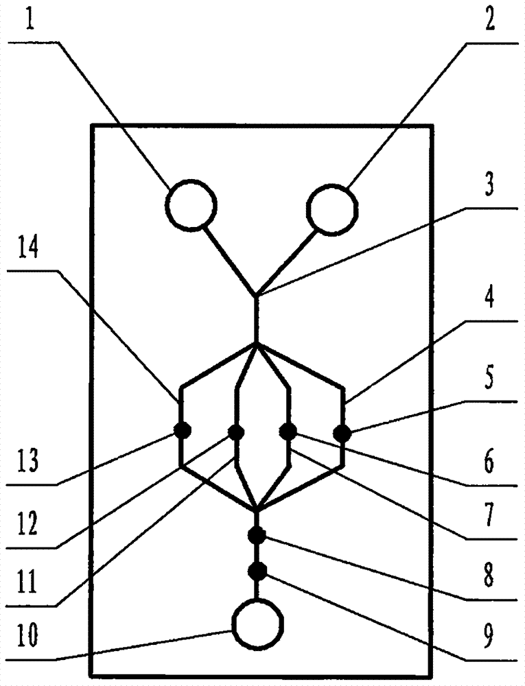
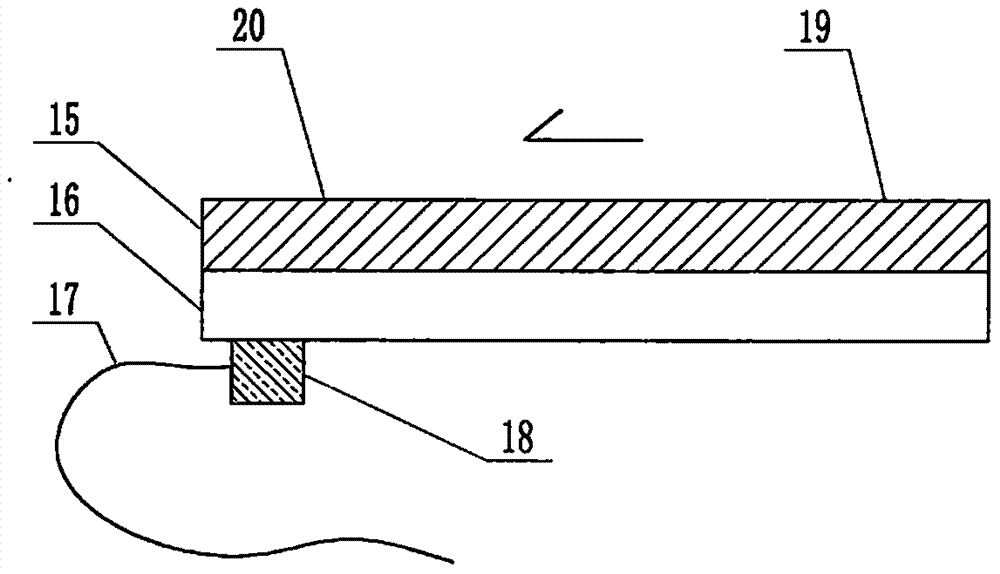
[0071] exist figure 1 and figure 2 In this example of the present case shown, the structure of the microfluidic device includes a multi-channel microfluidic chip, and the structure of the microfluidic chip includes a substrate 15 and a cover sheet 16 that are attached to each other and installed together. Both the substrate 15 and the cover sheet 16 are plates or sheets, and the side of the substrate 15 facing the cover sheet 16 contains a channel structure formed by a molding process or an etching process, and the substrate 15 also contains The window structure connected to the channel structure and pierced through the substrate is formed through a molding process, an etching process or a simple drilling process, and the substrate 15 and the cover sheet 16 that are attached to each other are jointly constructed into a structure containing The pipe structure and the microfluidic chip of the liquid pool structure connected thereto, the liquid pools are liquid pool 1, liquid p...


PUM

PropertyMeasurementUnit
Particle sizeaaaaaaaaaa
Diameteraaaaaaaaaa
Lengthaaaaaaaaaa

Abstract

The invention relates to a low-cost microfluidic device for syphilis diagnosis based on a novel liquid flow driving principle, which belongs to the field of analysis and testing. It is a technical goal to use cheap and easy-to-process polydimethylsiloxane (PDMS) as the substrate of the microfluidic chip for syphilis diagnosis; however, there are some difficult problems. The main point of this case is that the substrate is made of PDMS with an original ecological surface, and the pipes of the chip are filled with doped micron-sized titanium dioxide particles; the titanium dioxide particles are titanium dioxide that can induce superhydrophilic properties on the surface through pre-irradiation of visible light Particles; the collection of super-hydrophilic gaps between the particles of the titanium dioxide particle filler compensates and surpasses the original strong hydrophobic channels, thereby achieving a constant and super-hydrophilic modification effect; at the same time, with a small power The ultrasonic wave induces a difference in interfacial tension at the first and last ends of the chip, and then promotes the flow of the sample liquid along the channel of the chip to the direction of the terminal.

Description

technical field [0001] The invention relates to an inexpensive microfluidic device for syphilis diagnosis based on a novel liquid flow driving principle. The microfluidic device is a special device for diagnosing syphilis antigens based on antigen / antibody specific reactions, and belongs to the field of analysis and testing. Background technique [0002] For the technical background of multi-channel microfluidic syphilis diagnosis, please refer to CN 200910152141.4 and other invention patent applications. [0003] As far as the overall overview of microfluidic technology itself is concerned, you can refer to the monograph "Illustrated Microfluidic Chip Laboratory" published by the famous microfluidic expert Mr. Lin Bingcheng not long ago, which has been published by Science Press. The past, present, and future prospects of microfluidic technology, etc., have detailed and long-form discussions that go deep into specific details. [0004] So, let's talk about the key issues o...

Claims


Application Information

Patent Timeline
IPC IPC(8): B01L3/00G01N27/327G01N27/26G01N33/571
CPCB01L3/502707B01L3/50273B01L2300/0819B01L2400/0439G01N27/26G01N27/3275G01N33/571
Inventor 李榕生
Owner 李榕生
Why Eureka
Try Eureka