Full automated electronic coil tin dipping machine

A fully automated tin dipping machine technology, applied in tin feeding devices, metal processing equipment, manufacturing tools, etc., can solve the problem of inability to standard control tin dipping depth and tin dipping time and fixed-point positioning functions, poor surrounding environment of equipment, and work efficiency In order to improve processing safety, stable and reliable transportation, and improve processing quality

Active Publication Date: 2017-12-26
太仓新兰电子有限公司
View PDF8 Cites 1 Cited by
  • Summary
  • Abstract
  • Description
  • Claims
  • Application Information

AI Technical Summary

Problems solved by technology

[0002] Electronic coil 2 such as Figure 11 As shown, the electronic coil 2 needs to be soldered and dipped in tin during processing. Due to the many processes, manual loading is mostly used, and the electronic coil is picked up by clips and put into the dipping tin pool for tinning. This kind of operation is slow , it is impossible to standardly control the tin immersion depth, tin immersion time and fixed-point positioning function. Because liquid high-temperature sodium hydroxide and liquid high-temperature tin are dangerous goods, manual operation is very close to the source of danger, and safety poisoning accidents are likely to occur. Immersion tin is not easy to handle, and the surrounding environment of the equipment is also very poor, and the work efficiency is low

Method used


Image

  • Full automated electronic coil tin dipping machine
  • Full automated electronic coil tin dipping machine
  • Full automated electronic coil tin dipping machine

Examples


Embodiment Construction

[0039] In order to enable those skilled in the art to better understand the technical solutions of the present invention, the present invention will be described in detail below with reference to the accompanying drawings. The description in this section is only exemplary and explanatory and should not have any limitation on the scope of protection of the present invention. .

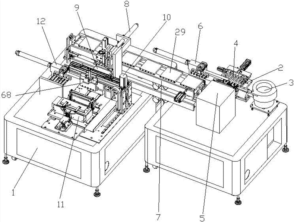
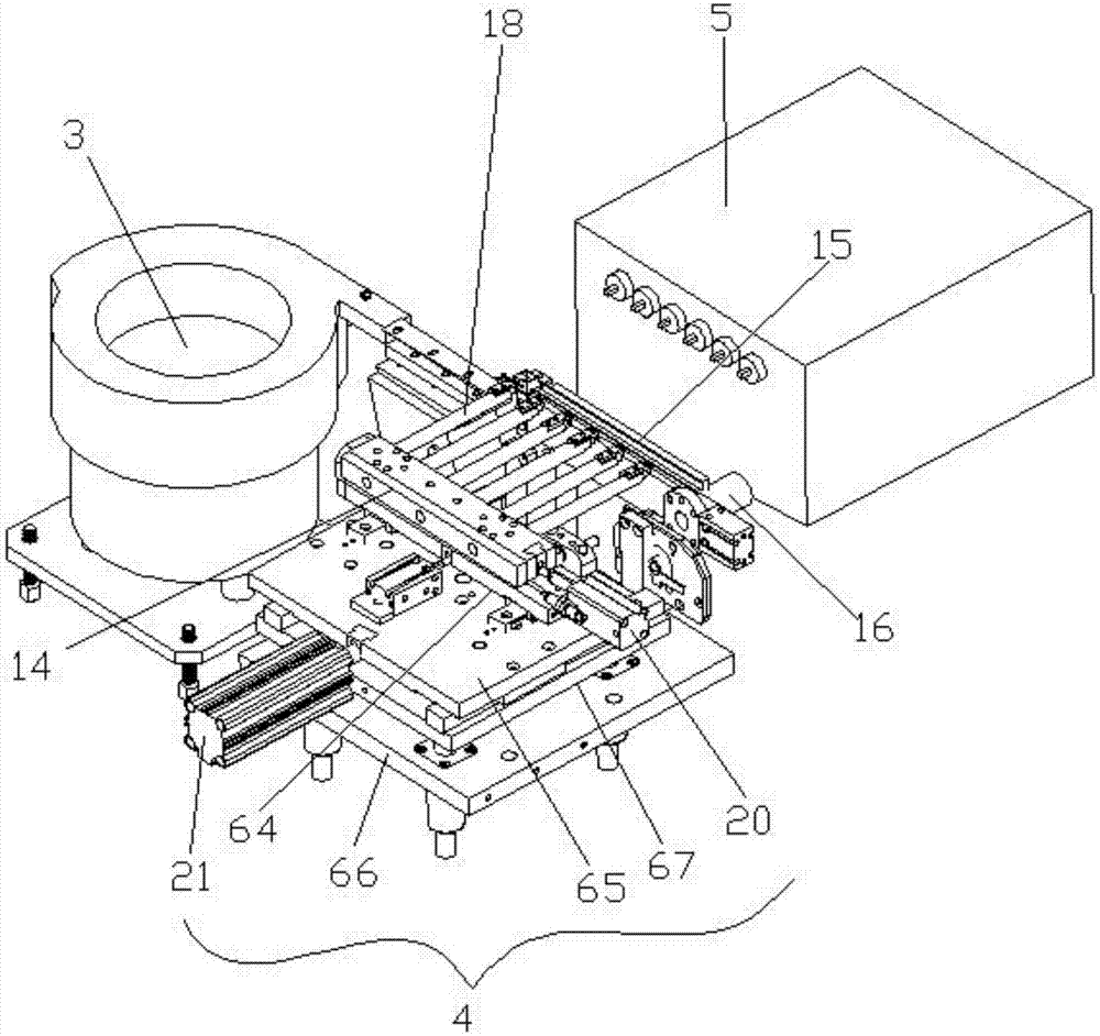
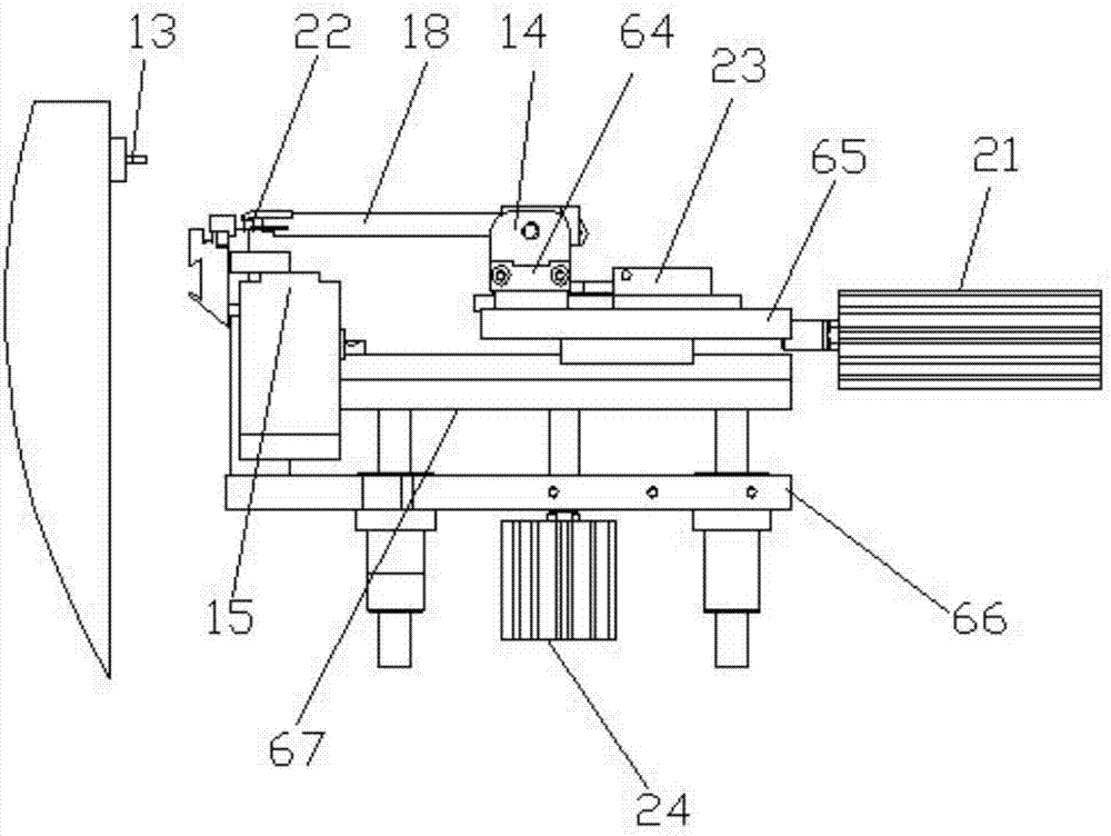
[0040] Such as Figure 1-Figure 14 As shown, the structural connection relationship of the present invention is: a fully automated electronic coil immersion tin machine, which includes a control box 1, and one end of the control box 1 is provided with a vibration plate 3 for transmitting the electronic coil 2. The vibration plate 3 The discharge end is provided with a positioning rail 15 for positioning the electronic coil 2; one side of the positioning rail 15 is provided with a butt welding clamp device 4, and the other side is provided with a butt welding box 5; the butt welding clamp device 4 is provid...


PUM


Abstract

The invention discloses a full automated electronic coil tin dipping machine. The full automated electronic coil tin dipping machine comprises a control box. One end of the control box is provided with a vibrating disc. The discharging end of the vibrating disc is provided with a positioning rail. One side of the positioning rail is provided with a butt-joint clamping device. The other side of the positioning rail is provided with a butt-joint box. The upper portion of the butt-joint clamping device is provided with a loading and unloading manipulator. A conveying belt is arranged on the side edge of the loading and unloading manipulator. The conveying belt is provided with a tool bearing plate. The tool bearing plate is internally and evenly provided with material pipes which are used for storing an electronic coil and penetrate through the two end surfaces of the tool bearing plate. The other side of the conveying belt is provided with a material clamping manipulator used for conveying the tool bearing plate. The lower portion of the material clamping manipulator is provided with a material passing device used for conveying the electronic coil in the tool bearing plate to a tin dipping manipulator. The front end of the material passing device is provided with the tin dipping manipulator and a blanking manipulator. The other side of the tin dipping manipulator is provided with a tin dipping device. By means of the full automated electronic coil tin dipping machine, electronic coil fixed-point tin dipping is completed through mechanical full automation controlling, the tin dipping efficiency of the electronic coil is greatly improved, the labor cost is reduced, and the producing efficiency is improved.

Description

Technical field [0001] The invention relates to the technical field of electronic coil processing, in particular to a fully automated electronic coil immersion tin machine. Background technique [0002] Electronic coil 2 such as Picture 11 As shown, the electronic coil 2 needs to be immersed in solder during processing. Due to the many processes, manual feeding and clamps are used to pick up the electronic coil and put the electronic coil into the immersion bath for soldering. This operation is slow , It is impossible to control the immersion tin depth, immersion tin time and fixed-point positioning function. Because liquid high temperature sodium hydroxide and liquid high temperature tin are dangerous goods, manual operation is very close to the source of danger, and safety poisoning accidents are prone to occur. Immersion tin is not easy to handle, and the surrounding environment of the equipment is also very poor, and the work efficiency is low. Therefore, it is necessary to ...

Claims


Application Information

Patent Timeline
IPC IPC(8): B23K3/06
CPCB23K3/0669B23K3/0676
Inventor 邓君杨坤
Owner 太仓新兰电子有限公司
Why Eureka
Try Eureka