Supercharge Your Innovation With Domain-Expert AI Agents!

Oil-water separation device for oil-containing sewage

An oil-water separation device and oil-water separation technology, which are applied in the directions of grease/oily substance/float removal device, liquid separation, separation method, etc., can solve the problems of blurred oil-water separation interface, poor oil-water separation accuracy, low processing efficiency, etc. The effect of reducing energy consumption, reducing energy consumption, and low energy consumption

Inactive Publication Date: 2017-12-26
四川沃兹凯兰科技有限公司
View PDF2 Cites 0 Cited by
  • Summary
  • Abstract
  • Description
  • Claims
  • Application Information

AI Technical Summary

Problems solved by technology

[0002] The working principle of the oil-water separator is mainly to carry out gravity separation based on the density difference of oil and water. However, because the process only relies on the density difference, the gravity separation process takes a long time and requires a large settlement area. The oil-water separation interface is blurred and the oil-water separation accuracy is high. Difference
Heating and aeration are auxiliary separation processes for the characteristics of oily sewage, but in the application process, in order to achieve a better treatment effect, a large amount of energy is often consumed
[0003] The conventional oil-water separation process adopts fiber ball filter, fiber bundle filter and ceramic membrane filter, etc., when the oil content in the sewage is high, and the oil is in a dispersed phase, the treatment efficiency is low and the effluent contains high sulfur.

Method used


Image

  • Oil-water separation device for oil-containing sewage

Examples


Embodiment Construction

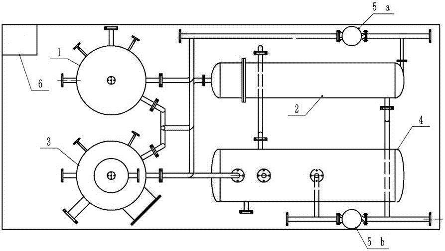
[0017] like figure 1 Shown is a schematic structural diagram of an oil-water separation device for oily sewage, including a PLC control system 6, and also includes a preheating tank 1, a heat exchanger 2, an oil-water separation and oil collection device 3, and a hot water storage tank 4. The above-mentioned PLC control system 6 is simultaneously connected with the valves at the water inlet of the preheating tank 1, the heat exchanger 2, the oil-water separation and oil collection device 3, and the hot water storage tank 4, the valves at the sewage outlet, and the valves at the water outlet. Electrically connected, the heat exchanger 2 is provided with a temperature measuring device and a heating device, and the temperature measuring device and the heating device are electrically connected to the PLC control system 6 at the same time. The oil-water separation and oil collection device 3 is provided with an electric heater and an aeration system, and the electric heater and aer...


PUM


Abstract

The invention belongs to the technical field of separation of oil-containing sewage of petrochemical industry, in particular to an oil-water separation device for oil-containing sewage. According to the oil-water separation device for the oil-containing sewage, a PLC control system is electrically connected with a valve at a sewage inlet, a valve at a sewage outlet and a valve at a water outlet of each of a preheating tank, a heat exchanger and an oil-water separation and oil collecting device; an oil-containing sewage conveying main pipeline is communicated with the sewage inlets of the preheating tank, the heat exchanger and the oil-water separation and oil collecting device; the heat exchanger is internally provided with an oil-containing sewage conveying pipeline and is connected with the sewage inlet of the heat exchanger; the sewage outlet of the preheating tank is communicated with the sewage inlet of the oil-water separation and oil collecting device; the water outlet of the oil-water separation and oil collecting device is communicated with the oil-containing sewage conveying main pipeline; the oil-containing sewage conveying main pipeline is provided with a pump I which is electrically connected with the PLC control system. The oil-water separation device for the oil-containing sewage disclosed by the invention reduces the energy consumption of the oil-water separation device, improves the oil-water separation efficiency, and can be widely applied to the separation of the oil-containing sewage of the petrochemical industry.

Description

technical field [0001] The invention belongs to the technical field of separation of petrochemical oily sewage, and in particular relates to an oil-water separation device for oily sewage. Background technique [0002] The working principle of the oil-water separator is mainly to carry out gravity separation based on the density difference of oil and water. However, because the process only relies on the density difference, the gravity separation process takes a long time and requires a large settlement area. The oil-water separation interface is fuzzy and the oil-water separation accuracy is high. Difference. Heating and aeration are auxiliary separation processes for the characteristics of oily sewage, but in order to achieve a better treatment effect during the application process, a large amount of energy is often consumed. [0003] The conventional oil-water separation process uses fiber ball filter or fiber bundle filter and ceramic membrane filter, etc. When the oil ...

Claims


Application Information

Patent Timeline
IPC IPC(8): C02F1/40C02F1/02
CPCC02F1/40C02F1/02
Inventor 韩志刚吕亮杨明军朱自强
Owner 四川沃兹凯兰科技有限公司
Features
  • R&D
  • Intellectual Property
  • Life Sciences
  • Materials
  • Tech Scout
  • Unparalleled Data Quality
  • Higher Quality Content
  • 60% Fewer Hallucinations
Learn More