
Composite aluminium alloy guard rail

An aluminum alloy, guardrail technology, applied in the direction of fences, roads, building types, etc., can solve problems such as only applicable, rough surface, sand holes, etc., to save costs, strengthen connectivity and impact resistance.

Active Publication Date: 2017-12-26
佛山市圣田智能科技有限公司
View PDF6 Cites 4 Cited by
  • Summary
  • Abstract
  • Description
  • Claims
  • Application Information

AI Technical Summary

Problems solved by technology

The manufacturing process of cast iron material determines that its surface is rough and has sand holes, which requires secondary grinding and mechanical reprocessing, and is prone to rust in the environment and affects the appearance. Its production efficiency is extremely low and causes environmental pollution.
The cost of stainless steel is very high, so the thickness is generally relatively thin, resulting in low weight and protection strength. If thicker stainless steel is used, the cost will be even higher
[0004] Aluminum alloy is a material that is easy to process, can produce many beautiful and smooth patterns on the surface, will not rust, and is much lower in cost than stainless steel. The strength of the alloy material is low, and the pure aluminum alloy material is not suitable for use on urban guardrails that require high protection strength
[0005] The Chinese patent "Steel-Aluminum Composite Profiles for Making Guardrails" (Notice No. CN 102434078A) records a kind of adding The guardrail made of matching steel lining is just a disguised form of adding a layer of aluminum alloy guardrail outside the steel-lined guardrail. This structure can only be used in indoor or garden areas with low protection strength requirements. On railings or handrails, it is not suitable for urban guardrails that require high protection strength

Method used


Image

  • Composite aluminium alloy guard rail
  • Composite aluminium alloy guard rail
  • Composite aluminium alloy guard rail

Examples


Embodiment Construction

[0033] The concept, specific structure and technical effects of the present invention will be clearly and completely described below in conjunction with the embodiments and accompanying drawings, so as to fully understand the purpose, characteristics and effects of the present invention. Apparently, the described embodiments are only some of the embodiments of the present invention, rather than all of them. Based on the embodiments of the present invention, other embodiments obtained by those skilled in the art without creative efforts belong to The protection scope of the present invention. In addition, all the connection / connection relationships mentioned in this article do not refer to the direct connection of components, but mean that a better connection structure can be formed by adding or reducing connection accessories according to specific implementation conditions. The various technical features in the invention can be combined interactively on the premise of not conf...


PUM


Abstract

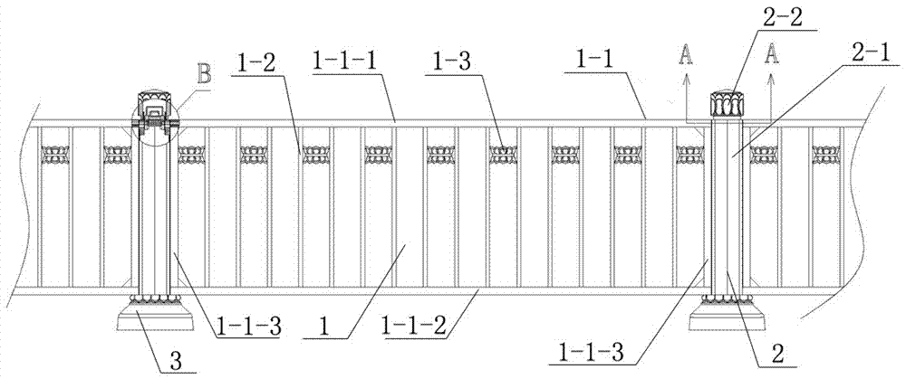
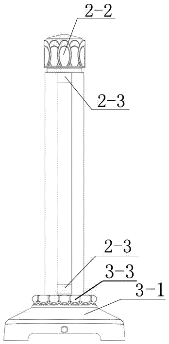
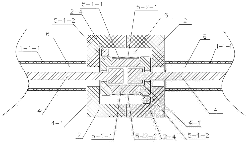
The invention discloses a composite aluminium alloy guard rail. The guard rail includes a composite base the inner layer iron core of which is completely wrapped by an aluminium alloy shell on the surface layer, aluminium alloy grid sheets and aluminium alloy columns are all provided with hollow channels communicated with one another, the hollow channel of each aluminium alloy grid sheet is internally provided with a steel reinforced rope, the hollow channel of each aluminium alloy column is internally provided with a steel self-locking clamping base, the clamping heads of the two steel reinforced ropes adjacent to each aluminium alloy column are placed in the inner cavity of the corresponding steel self-locking clamping base and fixedly locked, and the aluminium alloy columns are internally and fixedly provided with reinforced steel core rods in a lengthwise direction. Since the combined aluminium alloy guard rail is internally provided with a high-strength core framework net which is interlaced in the horizontal and vertical directions, only aluminium alloy profiles can be adopted on all the external portion and non-important portions of the combined aluminium alloy guard rail, and therefore not only can costs be greatly saved, but the guard rail is elegant in appearance and not likely to rust, and meanwhile, the stability and anti-shock resistance of the combined aluminium alloy guard rail are ensured.

Description

technical field [0001] The invention relates to the technical field of guardrails, in particular to an aluminum alloy composite guardrail. Background technique [0002] Now, protective fences are widely used in important facilities and places such as urban roads, the periphery of squares, and surrounding buildings for isolation, protection, and diversion. The guardrail should not only isolate the crowd but also isolate the vehicles, not only to prevent being pushed down by the crowd, but also to prevent the collision of the vehicle, even the unintentional or intentional collision of the high-speed vehicle, which puts a high demand on the impact strength of the guardrail. requirements. [0003] The material of existing metal guardrail has cast iron, stainless steel etc. The manufacturing process of cast iron material determines that its surface is rough and has sand holes, which requires secondary grinding and mechanical reprocessing, and is prone to rust in the environment...

Claims


Application Information

Patent Timeline
IPC IPC(8): E04H17/16E04H17/20E04H17/22E01F15/02
CPCE01F15/02E04H17/16E04H17/165E04H17/20E04H17/22
Inventor 周仲辉
Owner 佛山市圣田智能科技有限公司
Learn More