Non-shaft wave power generation device

A power generation device and wave energy technology, which is applied to ocean energy power generation, engine components, machines/engines, etc., can solve problems such as weak ability to capture wave energy, weak device anti-wave ability, difficult maintenance, etc., and achieve cost reduction Low energy consumption, improved energy conversion efficiency, and convenient installation

Inactive Publication Date: 2017-12-26
HAINAN UNIVERSITY +2
View PDF6 Cites 2 Cited by
  • Summary
  • Abstract
  • Description
  • Claims
  • Application Information

AI Technical Summary

Problems solved by technology

The oscillating water column type is driven by an air turbine, and its conversion efficiency is very low when the waves are small. At the same time, its shore-type application usually involves problems such as high engineering cost; the pendulum type technology is suitable for the characteristics of large thrust and low frequency of waves, and the frequency response The range is wide and the energy conversion efficiency is high, but the maintenance of its mechanical and hydraulic systems is relatively difficult. In order to adapt to the harsh marine environment such as typhoons, the emphasis is on ensuring high overall structural reliability and power generation stability, but the device is facing waves. The area is small, and the ability to capture wave energy is weak, resulting in a high cost per unit power; the canard technology has high energy conversion efficiency, but the ability to resist waves is weak, the reliability is poor, and it is easy to be damaged; the point absorption type The wave energy capture efficiency and energy conversion efficiency of the technology are relatively high, and the construction of the device is relatively simple, but it also has the disadvantage of weak wave resistance; the wave-surpassing technology has high energy conversion efficiency and high overall stability. Water turbine technology has become more common in the hydropower industry, and the survivability of the device is relatively high, but its engineering cost is relatively high

Method used


Image

  • Non-shaft wave power generation device
  • Non-shaft wave power generation device
  • Non-shaft wave power generation device

Examples


Embodiment Construction

[0021] The principles and features of the present invention are described below in conjunction with the accompanying drawings, and the examples given are only used to explain the present invention, and are not intended to limit the scope of the present invention.

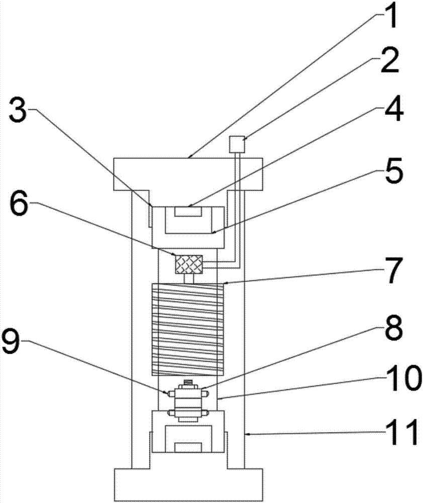
[0022] Such as figure 1 As shown, a shaftless wave energy power generation device includes an outer floating tube 11, a power generation tube 10, a magnetic group 8, a finishing circuit board 6 and an electrical device 2, and multiple sets of coils 7 are arranged outside the power generation tube 10, each The group coils 7 are all wound in multiple layers, and each layer of the coils 7 is separated by a non-metallic material, which is scotch tape or plastic film. The coil 7 includes at least one group, which can be a group of coils 7, or two groups or more than two groups, which can be set according to the size of the power generating device or the actual situation; the magnetic group 8 slides in the generator tube ...


PUM


Abstract

The invention discloses a non-shaft wave power generation device. The non-shaft wave power generation device comprises an outer floating tube, a power generation tube, a magnetic group, an arranging circuit board and an electricity utilization device; a plurality of coils are arranged outside the power generation tube, the magnetic group slides in the power generation tube, and the power generation tube is arranged in the outer floating tube in a sleeved mode; the two ends of the outer floating tube are sealed by outer floating tube caps; the arranging circuit board is arranged at one end of the power generation tube, and the arranging circuit board is electrically connected with the coils; the electricity utilization device is arranged outside the outer floating tube, and the arrangement circuit board is electrically connected with the electricity utilization device; and power generation tube caps, damping buffering isotropic magnets and damping buffering pads are sequentially arranged at the two ends of the power generation tube from outside to inside, and the power generation tube caps seal the two ends of the power generation tube. According to the non-shaft wave power generation device, a novel technology is adopted, and design of a non-shaft idler wheel reduces the friction force, improves the power generation efficiency, and prolongs the service life of the device.

Description

technical field [0001] The invention relates to the field of tidal energy power generation, in particular to a shaftless wave energy power generation device. Background technique [0002] At present, there are many kinds of existing wave energy generating devices, but there are many problems. The oscillating water column type is driven by an air turbine, and its conversion efficiency is very low when the waves are small. At the same time, its shore-type application usually involves problems such as high engineering cost; the pendulum type technology is suitable for the characteristics of large thrust and low frequency of waves, and the frequency response The range is wide and the energy conversion efficiency is high, but the maintenance of its mechanical and hydraulic systems is relatively difficult. In order to adapt to the harsh marine environment such as typhoons, the emphasis is on ensuring high overall structural reliability and power generation stability, but the devic...

Claims


Application Information

Patent Timeline
Patent Type & Authority Applications(China)
IPC IPC(8): F03B13/16
CPCF03B13/16Y02E10/30
Inventor 周衡林冬冬
Owner HAINAN UNIVERSITY
Why Eureka
Try Eureka