Wave energy power generating magnetic set and power generating device thereof

A power generation device and wave energy technology, applied in the direction of electromechanical devices, ocean energy power generation, electric components, etc., can solve the problems of weak ability to capture wave energy, weak device anti-wave ability, difficult maintenance, etc., and achieve low cost , improve energy conversion efficiency, and facilitate installation

Inactive Publication Date: 2017-12-29
HAINAN UNIVERSITY +2
View PDF4 Cites 2 Cited by
  • Summary
  • Abstract
  • Description
  • Claims
  • Application Information

AI Technical Summary

Problems solved by technology

The oscillating water column type is driven by an air turbine, and its conversion efficiency is very low when the waves are small. At the same time, its shore-type application usually involves problems such as high engineering cost; the pendulum type technology is suitable for the characteristics of large thrust and low frequency of waves, and the frequency response It has a wide range and high energy conversion efficiency, but the maintenance of its mechanical and hydraulic systems is relatively difficult. In order to adapt to the harsh marine environment such as typhoons, it focuses on ensuring high overall structural reliability and power generation stability. The area is small, and the ability to capture wave energy is weak, resulting in a high cost per unit power; the canard technology has high energy conversion efficiency, but the ability to resist waves is weak, the reliability is poor, and it is easy to be damaged; the point absorption type The wave energy capture efficiency and energy conversion efficiency of the technology are high, and the device construction is relatively simple, but it also has the disadvantage of weak wave resistance; the wave-surpassing technology has high energy conversion efficiency and high overall stability. Water turbine technology has become more common in the hydropower industry, and the survivability of the device is relatively high, but its engineering cost is relatively high

Method used


Image

  • Wave energy power generating magnetic set and power generating device thereof
  • Wave energy power generating magnetic set and power generating device thereof
  • Wave energy power generating magnetic set and power generating device thereof

Examples


Embodiment 1

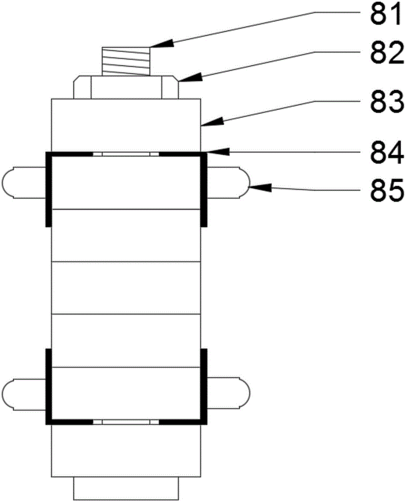
[0025] Such as figure 1 A wave energy generating electromagnetic group shown, the magnetic group 8 includes a plurality of magnets 83, the magnets 83 are cylindrical, with a through hole in the center, and the plurality of magnets 83 are fastened with bolts 81 and nuts 82 Together, and the magnet 83 is a strong NdFeB magnet 83, the magnetic group 8 can be provided with two magnets 83, or three or more magnets 83, depending on the implementation situation. A plurality of roller fixing devices 84 are arranged around the magnetic group 8, and a roller 85 is arranged on the roller fixing device 84. The roller 85 is a spherical roller, and the spherical roller adopts a material with light frictional resistance and a surface Coated with lubricant. Compared with the magnetic rotor of a general generator, the magnetic group 8 of the present invention has a simple structure, a saturated magnetic field, and a strong magnetic force, which can provide a saturated magnetic density for the...

Embodiment 2

[0027] see figure 1 , the structure of the magnetic group 8 in this embodiment is basically the same as that of the magnetic group 8 in Embodiment 1, the only difference is that the roller 85 is an annular roller, and the use of different rollers 85 provides more options for the present invention to adapt to the actual situation. In different situations, the ring-shaped roller is made of light-weight material with low frictional resistance, and the rolling direction of the ring-shaped roller is consistent with the bolt direction of the magnetic group 8, so that the magnetic group 8 can slide freely inside the power generation device, reducing a lot of resistance .

Embodiment 3

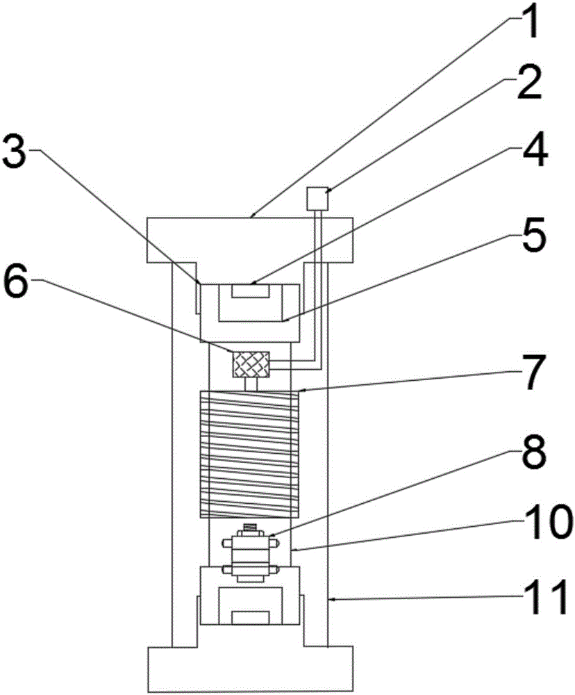
[0029] Such as figure 2 As shown, the present invention also provides a power generation device, including the magnetic group 8 of the above-mentioned embodiment, and the power generation device also includes an outer floating tube 11, a power generation tube 10, a magnetic group 8, a finishing circuit board 6 and an electrical device 2 , the generator tube 10 is wound with a multi-layer coil 7, and each layer of the coil 7 is separated by (clear tape or plastic film or) transparent non-metallic material, and the coil 7 includes at least one group, which can be a group of coils 7. Or two or more groups, which can be set according to the size of the power generation device or the actual situation; Both are sealed with the outer floating tube cap 1 to prevent seawater from entering the interior of the device to corrode parts. The electrical device 2 is arranged outside the outer floating tube 11; Cap 3, shock-absorbing buffer The same sex magnet 4 and shock-absorbing buffer pa...


PUM


Abstract

The invention discloses a wave energy power generating magnetic set and a power generating device thereof. The wave energy power generating magnetic set comprises a plurality of magnets. The magnets are cylindrical and are provided with through holes at the centers. The plurality of magnets are fastened together through bolts and nuts. The periphery of the magnet set is provided with a plurality of roller fixing devices. The roller fixing device is provided with a roller. The roller is spherical or annular. The power generating device comprises an external floating pipe, a power generating pipe, a sliding permanent magnet set, an arrangement circuit board and a power consumption device. A plurality of layers of coils are wound outside the power generating pipe. The sliding permanent magnet set slides in the power generating pipe. The external floating pipe sleeves the power generating pipe. Two ends of the external floating pipe are sealed by external floating pipe caps. The arrangement circuit board is arranged at one end of the power generating pipe. The arrangement circuit board is electrically connected with the coil. The power consumption device is arranged outside the external floating pipe. The arrangement circuit board is electrically connected with the power consumption device. Through utilizing innovative technology, the wave energy power generating magnetic set and the power generating device have advantages of reducing a friction force through a no-shaft roller, improving power generating efficiency and prolonging service life of the device.

Description

technical field [0001] The invention relates to the field of tidal energy power generation, in particular to a wave energy generating electromagnetic group and a generating device thereof. Background technique [0002] At present, there are many kinds of existing wave energy generating devices, but there are many problems. The oscillating water column type is driven by an air turbine, and its conversion efficiency is very low when the waves are small. At the same time, its shore-type application usually involves problems such as high engineering cost; the pendulum type technology is suitable for the characteristics of large thrust and low frequency of waves, and the frequency response It has a wide range and high energy conversion efficiency, but the maintenance of its mechanical and hydraulic systems is relatively difficult. In order to adapt to the harsh marine environment such as typhoons, it focuses on ensuring high overall structural reliability and power generation sta...

Claims


Application Information

Patent Timeline
Patent Type & Authority Applications(China)
IPC IPC(8): H02K7/18F03B13/14F03B13/26
CPCF03B13/14F03B13/26H02K7/1876Y02E10/30
Inventor 林冬冬周衡
Owner HAINAN UNIVERSITY
Why Eureka
Try Eureka