Eureka AIR delivers breakthrough ideas for toughest innovation challenges, trusted by R&D personnel around the world.

Apparatus capable of automatically monitoring exhaust emissions of vehicles on a real-time basis and assessment method

A tail gas emission and real-time monitoring technology, which is applied in the direction of measuring devices, traffic control systems, road vehicle traffic control systems, etc., can solve the problem of low detection accuracy of exhaust gas, and achieve the effect of improving accuracy and law enforcement efficiency

Inactive Publication Date: 2017-12-26
BEIJING LIHESHUNDA ELECTRONICS TECH
View PDF9 Cites 7 Cited by
  • Summary
  • Abstract
  • Description
  • Claims
  • Application Information

AI Technical Summary

Problems solved by technology

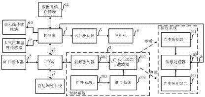
[0004] The purpose of the present invention is to solve the problem of low detection accuracy of traffic vehicle exhaust and automatic identification of vehicles with excessive exhaust emissions, and proposes a device and evaluation method for automatic real-time monitoring of traffic vehicle exhaust emissions, including a controller, FPGA, a transmitting system, and a receiving system , pan / tilt driver, camera, radar speed measuring system, RFID card reader, atmospheric pressure and temperature sensor, 4G wireless transmission module and data compensation storage table

Method used

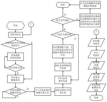
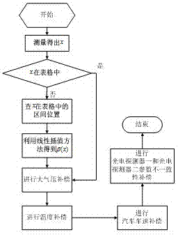

Image

  • Apparatus capable of automatically monitoring exhaust emissions of vehicles on a real-time basis and assessment method
  • Apparatus capable of automatically monitoring exhaust emissions of vehicles on a real-time basis and assessment method
  • Apparatus capable of automatically monitoring exhaust emissions of vehicles on a real-time basis and assessment method

Examples


Embodiment Construction

[0020] The present invention will be further described in detail below in conjunction with the accompanying drawings and specific embodiments.

[0021] figure 1 It is a structural schematic diagram of the device and evaluation method capable of automatic and real-time monitoring of traffic vehicle exhaust emissions of the present invention. The device and evaluation method that can automatically monitor traffic vehicle exhaust emissions in real time include: controller, FPGA, transmitting system, receiving system, pan-tilt driver, camera, radar speed measuring system, RFID card reader, atmospheric pressure and temperature sensor, 4G wireless transmission module and data compensation storage table. The transmitting system includes a radio frequency driver, an acousto-optic tunable filter and an infrared light source, and the receiving system includes a photodetector 1, a signal processor and a photodetector 2. The controller is connected with the transmitting system through F...


PUM


Abstract

The invention discloses an apparatus capable of automatically monitoring exhaust emissions of vehicles on a real-time basis and an assessment method. The apparatus comprises a controller, an FPGA, a transmitting system, a receiving system, a PTZ driver, a camera, a radar speed measuring system, an RFID reader, a barometric pressure and temperature sensor, a 4G wireless transmission module and a data compensation memory table, wherein the transmitting system comprises a radio frequency driver, an acousto-optic tunable filter, an infrared light source, and a collimation system, and the receiving system comprises a first photoelectric detector, a signal processor, and a second photoelectric detector. The method improves the accuracy of exhaust gas measurement by digitally compensating for the influence of barometric pressure, ambient temperature, traffic speed, and inconsistency of the parameters of the first photoelectric detector and the second photoelectric detector on the exhaust gas measurement precision. The RFID technology is used to quickly identify traffic vehicles with exhaust emission exceeding standard and report to the traffic control department on a real-time basis, thereby improving the law enforcement efficiency of relevant departments.

Description

technical field [0001] The invention relates to the technical field of environmental monitoring, in particular to a device and an evaluation method for automatic real-time monitoring of traffic vehicle tail gas emissions. Background technique [0002] With the rapid development of science and technology and the gradual improvement of people's living standards, the number of automobiles in large and medium-sized cities in China has increased rapidly, and the pollution of traffic vehicle exhaust has gradually become a hot spot for environmental protection departments. Accurate detection of traffic vehicle exhaust concentration is an important basis for the elimination of traffic vehicles. At present, the main traffic vehicle exhaust detection technologies include: chassis dynamometer test method, outdoor remote sensing detection method and vehicle exhaust detection method. Although the equipment cost of the chassis dynamometer test method is low, the test must be carried out u...

Claims


Application Information

Patent Timeline
IPC IPC(8): G08G1/017G08G1/052G01N21/3504
CPCG01N21/3504G08G1/017G08G1/052
Inventor 许常乐
Owner BEIJING LIHESHUNDA ELECTRONICS TECH
Why Eureka
Eureka Blog
Learn More