
Flexible conveying device, conveying manner therefore and baggage transporter with device

A transmission device and conveying device technology, which is applied in the field of luggage transfer vehicles, can solve problems such as inconvenient operation, low work efficiency, and high labor intensity, and achieve the effects of improving alignment accuracy, improving luggage stability, and reducing handling intensity

Inactive Publication Date: 2017-12-29
XIAMEN UNIV OF TECH +1
View PDF8 Cites 6 Cited by
  • Summary
  • Abstract
  • Description
  • Claims
  • Application Information

AI Technical Summary

Problems solved by technology

However, although the current luggage transfer vehicle solves the problem of luggage transfer between the aircraft and the ground, it is still inconvenient to operate when the luggage is loaded. When the luggage is loaded in the cabin, the existing luggage transfer vehicle can only transfer the luggage to the cabin. Luggage can only be transferred and stacked in the cabin by manual handling, while the interior height of the aircraft cargo compartment is only 1.5m, and the handling distance is more than 20 meters. Occupational diseases such as shoulder, waist and leg injuries of workers
[0004] In order to solve the above problems, the patent application 201710034439.X proposes a transmission device. The transmission device includes a drum type transmission device, a belt end transmission device and a connector. The belt end transmission device is connected to a drum type transmission device through the connector. The flexible structure of the device realizes the stacking of luggage at different positions in the cabin. Obviously, the above structure can improve the efficiency of luggage transportation to a certain extent, but there are still some problems. The device often has to load the luggage at the entrance and then drag it to the destination. Therefore, , it is necessary to continuously transport the luggage back and forth when releasing the luggage; on the other hand, although the conveyor at the end of the belt can realize lifting, but after the belt is raised, it is sometimes not long enough to reach the place where the luggage is stacked at a high place, and the above-mentioned device needs to be further improved

Method used


Image

  • Flexible conveying device, conveying manner therefore and baggage transporter with device
  • Flexible conveying device, conveying manner therefore and baggage transporter with device
  • Flexible conveying device, conveying manner therefore and baggage transporter with device

Examples


Embodiment 1

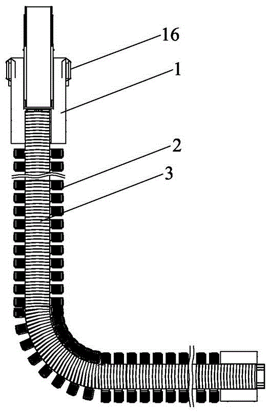
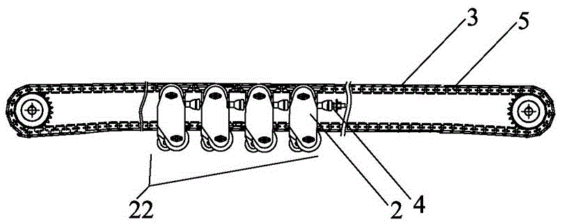
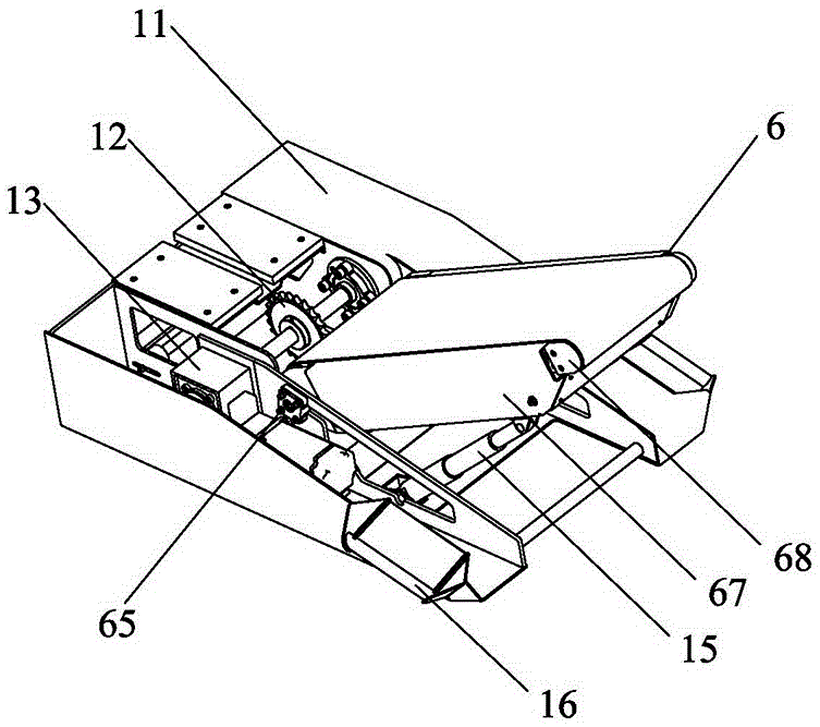
[0039] The present invention discloses a flexible transmission device, such as Figure 1-2 As shown, it is a preferred embodiment of the present invention. The flexible transmission device includes a walking device 1, a plurality of support units 2 and a plurality of side-curved conveyor chain plates 3, wherein the support units 2 are sequentially connected and arranged in a line through universal joint bearings 4. A support device 22 that can bend and advance, a closed loop side bending chain 5 connects each support unit 2 in series from the top and bottom of the support device 22 along the axial direction of the support device 22 at the same time, and the walking device 1 is arranged at one end of the support device 22 to form a flexible transmission device The head of the side bending conveying chain plate 3 is fixed on the outside of the side bending chain 5 to form an annular closed chain plate circle; Further, in order to make the cargo and luggage on the chain plate cir...

Embodiment 2

[0051] Such as Figure 9 As shown, a baggage transfer vehicle includes a vehicle 9 and a transfer device installed on the vehicle 9, wherein the transfer device includes a main transfer device 91 and a flexible transfer device 92 as described in Embodiment 1, in order to solve the problem caused by diesel power Environmental issues such as exhaust pollution, noise pollution, etc., and in order to avoid the impact of vibration on the stability of the luggage delivery vehicle during engine operation, this embodiment uses an electric vehicle as the main body of the vehicle 9. The electric vehicle includes a front 93 and an automobile chassis positioned at the rear of the front. 94, the electric driving device 95 that drives the car to move ahead is fixedly installed on the both sides top of chassis 94. Wherein, the main conveying device 91 is a strip-shaped conveying mechanism with a main conveying belt 98 , which can realize continuous two-way conveying of goods on the main conv...


PUM


Abstract

The invention discloses a flexible conveying device, a conveying manner of the device and a bagged transporter with the device. The device comprises a walking device, multiple bearing units and multiple side bending conveying chain plates; the bearing units are sequentially connected through universal joint bearings to form a bearing device capable of advancing in a bending manner, the walking device is arranged at one end of the bearing device to form the head of the flexible conveying device, and a closed annular side bending chain and the side bending conveying chain plates fixed to the outer side of the side bending chain are in series connection with the supporting units to form a driving chain plate ring. Straight-line conveying of cargo luggage is adjusted to bending path conveying in any direction, cargos can be directly conveyed to reach the any corner in a cabin, point-to-point transport needs can be met, the carrying strength is reduced, in cooperation with a lifting mechanism and a telescopic mechanism, the device can improve the alignment precision of the luggage loading point and the unloading point, and work efficiency is improved.

Description

technical field [0001] The invention relates to the field of object conveying and transportation, in particular to a flexible conveying device, its conveying method and a baggage conveying vehicle carrying the device. Background technique [0002] At present, with the rapid development of my country's aviation industry, the number of airports in my country is also increasing rapidly. At the same time, the continuous increase of bulk cargo transportation in many airports makes the demand for luggage delivery vehicles in various airports more and more. Patent ZL200710047377.2 discloses the basic structure of the existing baggage transfer vehicle in my country. The baggage transfer vehicle is generally composed of a body and a liftable transfer frame installed on the body. The transfer frame is jointly driven by the hydraulic system and the electrical system to realize the connection between the aircraft in the airport and the ground. transfer of luggage. [0003] Obviously, th...

Claims


Application Information

Patent Timeline
IPC IPC(8): B65G21/14B65G21/22B65G21/20B65G17/06B64F1/32
CPCB64F1/32B65G17/068B65G21/14B65G21/2045B65G21/22
Inventor 欧阳联格韩锋钢郑宁徐永明戚玉柱
Owner XIAMEN UNIV OF TECH
Learn More