Low temperature pump

A cryopump, low temperature technology, applied in pumps, pump components, variable capacity pump components, etc., can solve the problems of limiting the adsorption limit of cryopumps, gas adsorption, poor condensation effect, etc., and achieve optimized adsorption/condensation limit, optimized adsorption /Condensing efficiency, the effect of structure optimization

Pending Publication Date: 2017-12-29
VACREE TECH
View PDF16 Cites 4 Cited by
  • Summary
  • Abstract
  • Description
  • Claims
  • Application Information

AI Technical Summary

Problems solved by technology

Under the condition that the opening area of ​​the gas inlet is relatively limited, for the cryopump deep in the inner cavity of the cryopump, because it is far away from the suction port, the gas adsorption and condensation effects are poor, which in turn limits the adsorption limit of the entire cryopump

Method used


Image

  • Low temperature pump
  • Low temperature pump
  • Low temperature pump

Examples


Embodiment 1

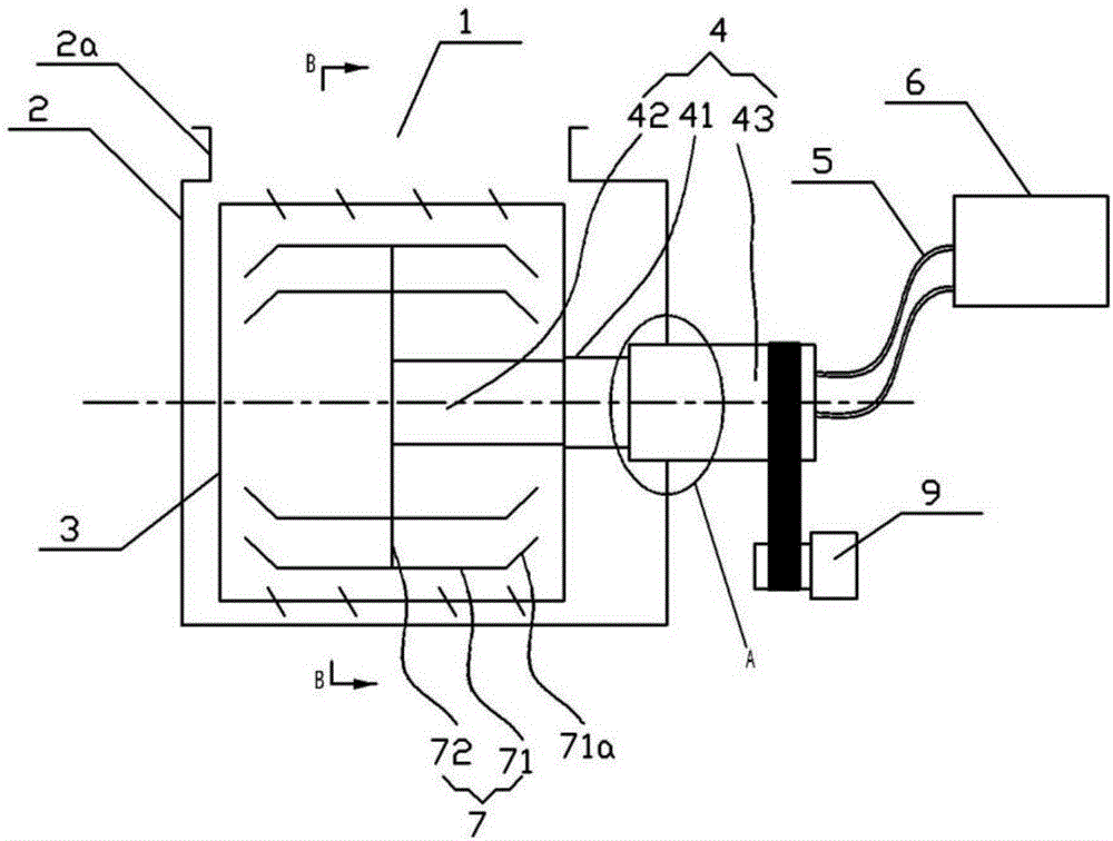
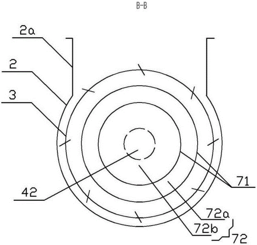
[0023] Such as Figure 1 to Figure 3 As shown, the cryopump is installed in the vacuum chamber for raising the vacuum degree in the vacuum chamber to a desired level. The cryopump has a suction port 1 for receiving gas from the vacuum chamber. The cryopump includes a housing 2 , a radiation cold shield 3 , a low-temperature cold source, and a cryopanel assembly 7 .

[0024] The shell 2 of the cryopump is roughly cylindrical with cover plates at both ends, and its axis is coaxial with the cold head of the low-temperature cold source. An opening 2a connected to the vacuum cavity (ie, the suction port of the cryopump) is provided on the side of the casing 2 . The opening is also cylindrical and extends outward in the radial direction of the cryopump, and the top end of the opening has a flange structure. The opening is preferably in the shape of a square tube.

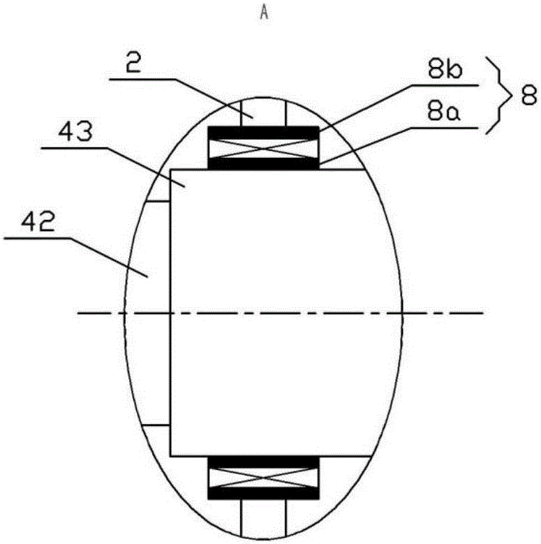
[0025] The low-temperature cold source is a two-stage GM refrigerator, which includes a helium compressor 6 and a c...

Embodiment 2

[0032]Embodiment 2 is roughly the same as Embodiment 1 in structure composition and connection mode of the cryopump. The difference is that the cryopanel assembly 7 is improved on the basis of the first embodiment, and the cryopanel assembly 7 includes a cryogenic cylinder 71 and a cryogenic vane 73 . The cryogenic cylinder 71 is nested and installed on the secondary cooling platform and is thermally connected with it. There are a plurality of low-temperature blades 73 , which are thermally connected and installed on the surface of the low-temperature cylinder 71 , and are arranged at certain intervals in the circumferential and longitudinal directions of the outer surface of the low-temperature cylinder 73 . As mentioned above, the larger the angle between the direction of the gas inlet and the plane of the low-temperature vane (that is, the closer to the vertical angle direction), the better the condensation and adsorption effect of the low-temperature vane. If the cryogeni...


PUM


Abstract

The invention discloses a low temperature pump installed in a vacuum cavity. The low temperature pump comprises a shell, a low temperature cold source, a radiation cold shield located in the shell and a low temperature plate assembly surrounded by the radiation cold shield. The low temperature cold source comprises a cold head and a compressor which are connected through a pipeline. The cold head comprise a secondary cooling table, a primary cooling table and a cold head base which are connected in sequence. The radiation cold shield is fixedly installed on the primary cooling table and is in thermal connection with the primary cooling table. The low temperature plate assembly is fixedly installed on the secondary cooling table and is in thermal connection with the secondary cooling table. The shell of the low temperature pump is in the shape of a barrel with a main shaft, the side face of the barrel is provided with a low temperature pump air suction inlet, and the cold head base is movably installed on the shell and can be rotated around a main shaft of the low temperature pump relative to the shell. By means of rotational design of the low temperature plate assembly and the radiation cold shield, the adsorption and condensation limit and efficiency of the low temperature pump are improved.

Description

technical field [0001] The invention belongs to the technical field of low-temperature refrigeration, and in particular relates to a low-temperature pump with a relatively high adsorption limit. Background technique [0002] A cryopump is a vacuum pump that condenses gas on a low-temperature surface, also known as a condensation pump. Cryopumps can obtain a clean vacuum with the highest pumping rate and the lowest ultimate pressure, and are widely used in the research and production of semiconductors and integrated circuits, as well as molecular beam research, vacuum coating equipment, vacuum surface analysis instruments, ion implanters and space simulation devices, etc. aspect. [0003] In daily use, the cryopump is installed in the vacuum chamber of the vacuum processing device. Since the cryopump adopts the cold head to absorb, after working for a period of time, the cryopanel on the cold head is covered by solid gas condensed, the surface temperature rises, the adsorpt...

Claims


Application Information

Patent Timeline
Patent Type & Authority Applications(China)
IPC IPC(8): F04B37/10F04B39/06F04B39/00
CPCF04B37/10F04B39/00F04B39/06
Inventor 武义锋邓家良冯苌春曾环王少恒张海峰俞杰孙志和
Owner VACREE TECH
Why Eureka
Try Eureka