
Method for separating and identifying composite fault features of wind power transmission chain

A technology of compound fault and identification method, applied in machine gear/transmission mechanism testing, measuring devices, instruments, etc., can solve problems such as low precision, no relevant evaluation indicators for decomposed sub-bands, long calculation time, etc.

Active Publication Date: 2017-12-29
INST OF ELECTRICAL ENG CHINESE ACAD OF SCI
View PDF17 Cites 9 Cited by
  • Summary
  • Abstract
  • Description
  • Claims
  • Application Information

AI Technical Summary

Problems solved by technology

This patent uses the wavelet packet method to realize the noise reduction of the signal and the accurate judgment of the fault or not, but it cannot really realize the separation and identification of the modulated composite fault
Chinese Invention Patent CN102937522A "A Gearbox Composite Fault Diagnosis and System" adopts the double-tree complex wavelet transform method to decompose the signal to obtain multiple sub-bands, and uses the energy operator method to analyze the signals of each sub-band respectively to extract fault features. Although this patent can Identify complex faults, but since the decomposed sub-band signals have no relevant evaluation indicators, each sub-band signal needs to be processed sequentially, resulting in long calculation time and low accuracy results
The literature "Application of LMD Adaptive Multi-scale Morphology and Teager Energy Operator Method in Bearing Fault Diagnosis" proposes to use LMD (local mean decomposition method) to decompose into multiple sub-band signals, and use multi-scale morphological filtering to filter each sub-band After the processing, the energy operator is used to demodulate to obtain the characteristic frequency of the bearing fault. This method can effectively extract the fault information, but there is also the problem that there is no relevant evaluation index for the decomposed sub-bands, and each sub-band signal needs to be processed sequentially. , causing the problem of long calculation time and low precision

Method used


Image

  • Method for separating and identifying composite fault features of wind power transmission chain
  • Method for separating and identifying composite fault features of wind power transmission chain
  • Method for separating and identifying composite fault features of wind power transmission chain

Examples


Embodiment Construction

[0073] The present invention will be further described below in conjunction with the accompanying drawings and specific embodiments.

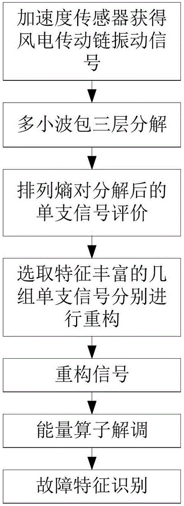
[0074] Such as figure 1 As shown, the steps of the composite fault feature separation and identification method of the present invention are as follows:

[0075] 1. Use the vibration acceleration sensor to collect the vibration signal x(t) of the wind power transmission chain, where t represents the time corresponding to the collected signal;

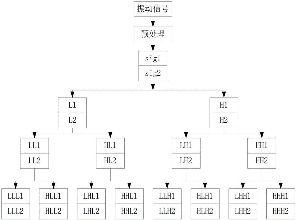
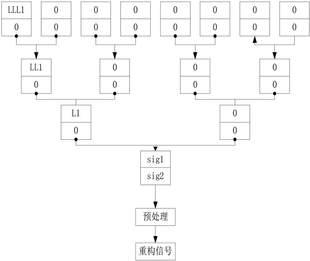
[0076] 2. Using the multi-wavelet packet method to decompose the vibration signal x(t), the process is as follows figure 2 As shown, the details are as follows:

[0077] (1) Carry out multi-wavelet preprocessing to the vibration signal x(t);

[0078] Because the signal x(t) is a one-dimensional signal, and the multi-wavelet generally includes multiple scaling functions and wavelet functions, the repeated sampling method is used to perform multi-wavelet preprocessing on the vibration signal x(t) to ob...


PUM


Abstract

A method for separating and identifying composite fault features of a wind power transmission chain includes the following steps of: obtaining a vibration signal by using an acceleration sensor; decomposing the acquired vibration signal in a whole frequency range by using multi-wavelet packet transform; by using a permutation entropy as an evaluation index, selecting single signals satisfying requirements to perform reconstruction to complete signal noise reduction and composite fault separation; and processing the reconstructed signals by using an energy operator demodulation method to identify fault information.

Description

technical field [0001] The invention relates to a method for separating composite fault features of a wind power transmission chain. Background technique [0002] With the rapid development of wind power generation technology, the functions of wind power equipment have become stronger, larger, and more intelligent, and the corresponding operation and maintenance costs have also been increasing. With the increase in the service time of wind turbines, the failure rate has increased significantly. Statistics prove that, Faults are mainly concentrated in the wind power electrical control system, transmission system, blades and other components. Once a failure occurs, it will cause downtime and bring huge economic losses. Among them, the failure of the transmission system will cause the longest downtime for maintenance. Therefore, it is necessary to repair the wind power transmission chain system. Monitor and diagnose the operating status of the system. [0003] In actual operat...

Claims


Application Information

Patent Timeline
IPC IPC(8): G01M13/02
CPCG01M13/028
Inventor 马本栋胡书举宋斌孟岩峰
Owner INST OF ELECTRICAL ENG CHINESE ACAD OF SCI
Learn More