
Multi-wavelength multiplexing structure suitable for optical fiber communication technical field

A technical field, the technology of optical fiber communication, which is applied in the field of multi-wavelength multiplexing structure, can solve the problems of large occupied space and large volume of multiplexing devices, and achieve the effect of flexible distribution and favorable coupling debugging

Inactive Publication Date: 2017-12-29
CHENGDU JOINCORE FIBER COMM EQUIP CO LTD
View PDF3 Cites 5 Cited by
  • Summary
  • Abstract
  • Description
  • Claims
  • Application Information

AI Technical Summary

Problems solved by technology

[0005] At present, in the existing multi-wavelength multiplexing optical modules, the laser chips for the four different wavelength optical signals are individually packaged in their respective diodes, and are placed on the same plane during application, so that the overall occupation If the space is large, the volume of the final combined wave device will be relatively large

Method used


Image

  • Multi-wavelength multiplexing structure suitable for optical fiber communication technical field
  • Multi-wavelength multiplexing structure suitable for optical fiber communication technical field
  • Multi-wavelength multiplexing structure suitable for optical fiber communication technical field

Examples


Embodiment 1

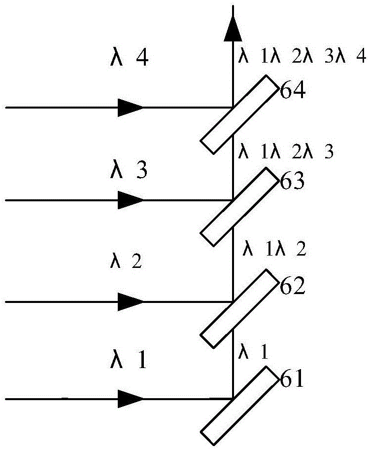
[0043] like figure 1 As shown, the present invention is an existing optical module for multi-wavelength multiplexing, which multiplexes four optical signals of four wavelengths λ1, λ2, λ3, and λ4, and the optical signal of λ1 wavelength is subjected to the first wavelength division multiplexing After being reflected by the diaphragm 61, it reaches the second wavelength division multiplexing diaphragm 62, and the second wavelength division multiplexing diaphragm 62 multiplexes the λ2 wavelength optical signal and the λ1 wavelength optical signal to become the λ1λ2 wavelength optical signal, and the third wavelength division multiplexing Using the diaphragm 63 to multiplex the λ3 wavelength optical signal and the λ1λ2 wavelength optical signal to obtain the λ1λ2λ3 wavelength optical signal, the fourth wavelength division multiplexing diaphragm 64 multiplexes the λ4 wavelength optical signal and the λ1λ2λ3 wavelength optical signal to obtain the λ1λ2λ3λ4 wavelength optical signal,...

Embodiment 2

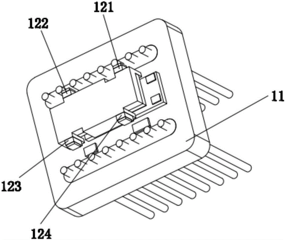
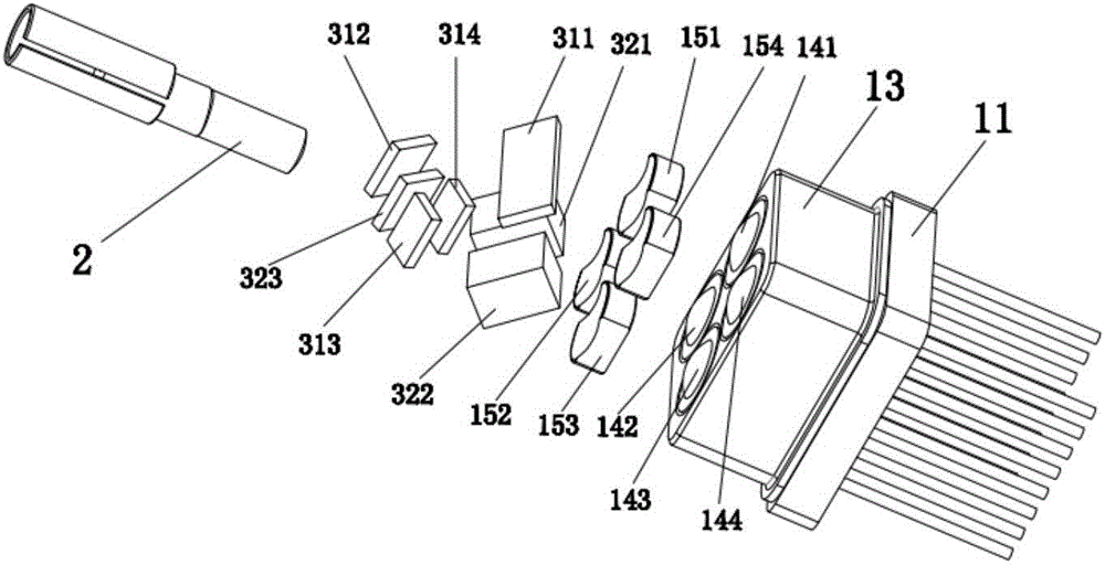
[0045] like Figure 2 to Figure 5 As shown, it is a multi-wavelength multiplexing structure suitable for the field of optical fiber communication technology of the present invention, including a transmitting end 1, an output end 2, an optical component 3, an optical component fixing device 4, and a housing 5, and the transmitting end 1 includes laser diodes connected in sequence 11, laser chip group, tube cap 13 and collimating lens group, output port 2 is the output port of optical signal, optical assembly 3 comprises reflective mirror group and multiplex filter group; Laser chip group comprises the first laser chip 121, the second Laser chip 122, the 3rd laser chip 123, the 4th laser chip 124, collimating lens group comprises collimating positive lens group, collimating positive lens group comprises the first collimating positive lens 141, the second collimating positive lens 142, the 3rd collimating positive lens 143, the fourth collimating positive lens 144, the reflector ...

Embodiment 3

[0049] The present invention is based on embodiment 2, and the present invention is further described.

[0050] like Image 6 As shown, the tube cap 13 of the laser diode 11 at the transmitting end 1 is a tube cap with a lens, and the collimating lens group can be a single lens to directly collimate the diverging laser beam. The first collimating positive lens 141 of the collimating lens group, The second collimating positive lens 142, the third collimating positive lens 143, and the fourth collimating positive lens 144 are three-dimensionally distributed on the tube cap 13 of the laser diode 11. The optical principle is as follows: Figure 7 As shown, the first laser chip 121 is selected as an example, and the divergent beam emitted by the first laser chip 121 becomes a parallel beam after passing through the first collimating positive lens 141 .


PUM


Abstract

The present invention discloses a multi-wavelength multiplexing structure suitable for the optical fiber communication technical field. The multi-wavelength multiplexing structure comprises a transmitting end, an output end, an optical assembly, an optical assembly fixing device and a shell; the transmitting end comprises a laser diode, a laser chipset, a tube cap and a collimating lens group; the output end is an output port of optical signals; the optical assembly comprises a reflector group and a combining filter group; the collimating lens group collimates divergent laser beams emitted by the laser chipset to generate four optical signals of parallel light beams; a first combining filter combines the first optical signal lambda1 with the second optical signal lambda2; a second combining filter combines the third optical signal lambda3 with the fourth optical signal lambda4; and the third combining filter multiplexes the four optical signals and outputs the optical signals from the output end. According to the multi-wavelength multiplexing structure of the invention, the spatial three-dimensional distribution of a plurality of chips is used, the spatial three-dimensional distribution of the combining filters and reflectors is used in combination, and therefore, the multi-wavelength combination of an ultra-small space can be realized with a simple process at a lower cost.

Description

technical field [0001] The invention relates to the technical field of optical fiber communication, in particular to a multi-wavelength multiplexing structure suitable for the technical field of optical fiber communication in the technical field of optical fiber communication. Background technique [0002] Due to the rapid development of optical fiber communication, with the increase in the demand for transmission capacity of a single optical fiber, such as real-time transmission of video images in virtual reality (VR) and augmented reality (AR), it is directly required to maximize the width of the optical fiber. Wavelength Division Multiplexing (WDM) technology is one of the key technologies for improving transmission capacity. A WDM system multiplexes a plurality of optical signals whose respective wavelengths are different from each other. In recent years, WDM of optical modules has been demanded. For example, TOSA as an optical module for an optical module having a ligh...

Claims


Application Information

Patent Timeline
Patent Type & Authority Applications(China)
IPC IPC(8): G02B6/293G02B6/32G02B6/42
CPCG02B6/2938G02B6/32G02B6/4249G02B6/4251
Inventor 赖成军
Owner CHENGDU JOINCORE FIBER COMM EQUIP CO LTD
Learn More