A thermal control device for a fuel storage tank
A storage tank and fuel technology, applied in the field of thermal control devices for fuel storage tanks, can solve problems such as thermal control requirements for bicomponent propellant storage tanks, and achieve the effects of flexible design, simple process, and low cost
Active Publication Date: 2016-09-07
SHANGHAI SATELLITE ENG INST
View PDF0 Cites 3 Cited by
- Summary
- Abstract
- Description
- Claims
- Application Information
AI Technical Summary
Problems solved by technology
The purpose of the present invention is in order to solve the problem of the thermal control demand of bicomponent propellant storage tank, propose a kind of thermal control device of fuel storage tank, especially adapt to the engine of 490N
Method used
View moreImage
Smart ImageViewing Examples
Examples
Embodiment Construction
Login to View More PUM
 Abstract
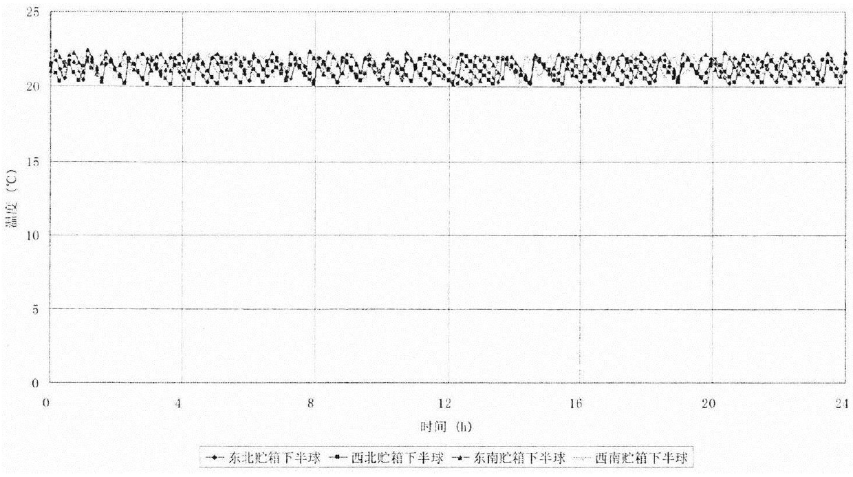
The invention provides a thermal control device for an engine fuel storage tank, comprising: a multi-layer structure, a thermal insulation gasket, a heater and a thermistor. It includes that the multi-layer structure is wrapped on the hemispherical surface and the column section of the fuel tank, the upper and lower sides of the tank mounting plate, and the corresponding surface of the tank support rod. The multi-layer structures are 10-unit, 5-unit, and 5-unit multi-layer heat insulation components respectively, and each multi-layer heat insulation unit is composed of double-sided aluminized polyester film and nylon net towel. According to the results of previous dynamic load satellite heat balance tests, combined with the staged consumption characteristics of propellant in orbit, in addition to heat insulation installation and all-layer coating, the present invention focuses on thermal compensation control on the lower ball section and installation area of the storage tank to meet the Thermal control requirements for bipropellant tanks. It meets the high-precision temperature control requirements of satellite fuel storage tanks, and at the same time adapts to the temperature requirements of the transfer orbit section and the normal on-orbit section, with good reliability and flexible design.
Description
technical field The technical field of the aerospace and aviation of the present invention, in particular, relates to a thermal control device for a fuel storage tank. Background technique Bicomponent propulsion systems were first launched in the mid-1970s and were widely used by the 1980s. The engine module of this system is composed of a 490N two-component liquid apogee engine and 16-18 10N thrusters. They use the same pressure and propellant control system. The pipeline in front of the engine valve is divided into an apogee and an attitude control engine. It is characterized by high specific stroke and large payload. Through the multiple ignition performance of the liquid apogee engine, the accuracy of orbiting is greatly improved. Further, the propellant storage module of the propellant control system mainly includes 4 propellant storage tanks, 8 self-locking valves, 2 normally open electric explosion valves, 4 filling and discharging valves, 4 pressure sensors and se...
Claims
Login to View More Application Information
Patent Timeline
 Patent Type & Authority Patents(China)
IPC IPC(8): F02K9/60B64D37/06
Inventor 付鑫郭涛康奥峰江世臣
Owner SHANGHAI SATELLITE ENG INST
Features
- R&D
- Intellectual Property
- Life Sciences
- Materials
- Tech Scout
- Unparalleled Data Quality
- Higher Quality Content
- 60% Fewer Hallucinations
Learn More Browse by: Latest US Patents, China's latest patents, Technical Efficacy Thesaurus, Application Domain, Technology Topic, Popular Technical Reports.
© 2025 PatSnap. All rights reserved.Legal|Privacy policy|Modern Slavery Act Transparency Statement|Sitemap|About US| Contact US: help@patsnap.com


