
Efficient fused road coating mixing device

A mixing device and road technology, applied in mixers, mixing methods, fluid mixers, etc., can solve the problems of uneven mixing and low utilization rate of powder materials, and achieve improved mixing uniformity, high utilization rate of powder materials, high utilization rate of powder materials, etc. The effect of increasing the contact area

Inactive Publication Date: 2018-01-02
长兴小浦凯荣机械加工厂
View PDF1 Cites 2 Cited by
  • Summary
  • Abstract
  • Description
  • Claims
  • Application Information

AI Technical Summary

Problems solved by technology

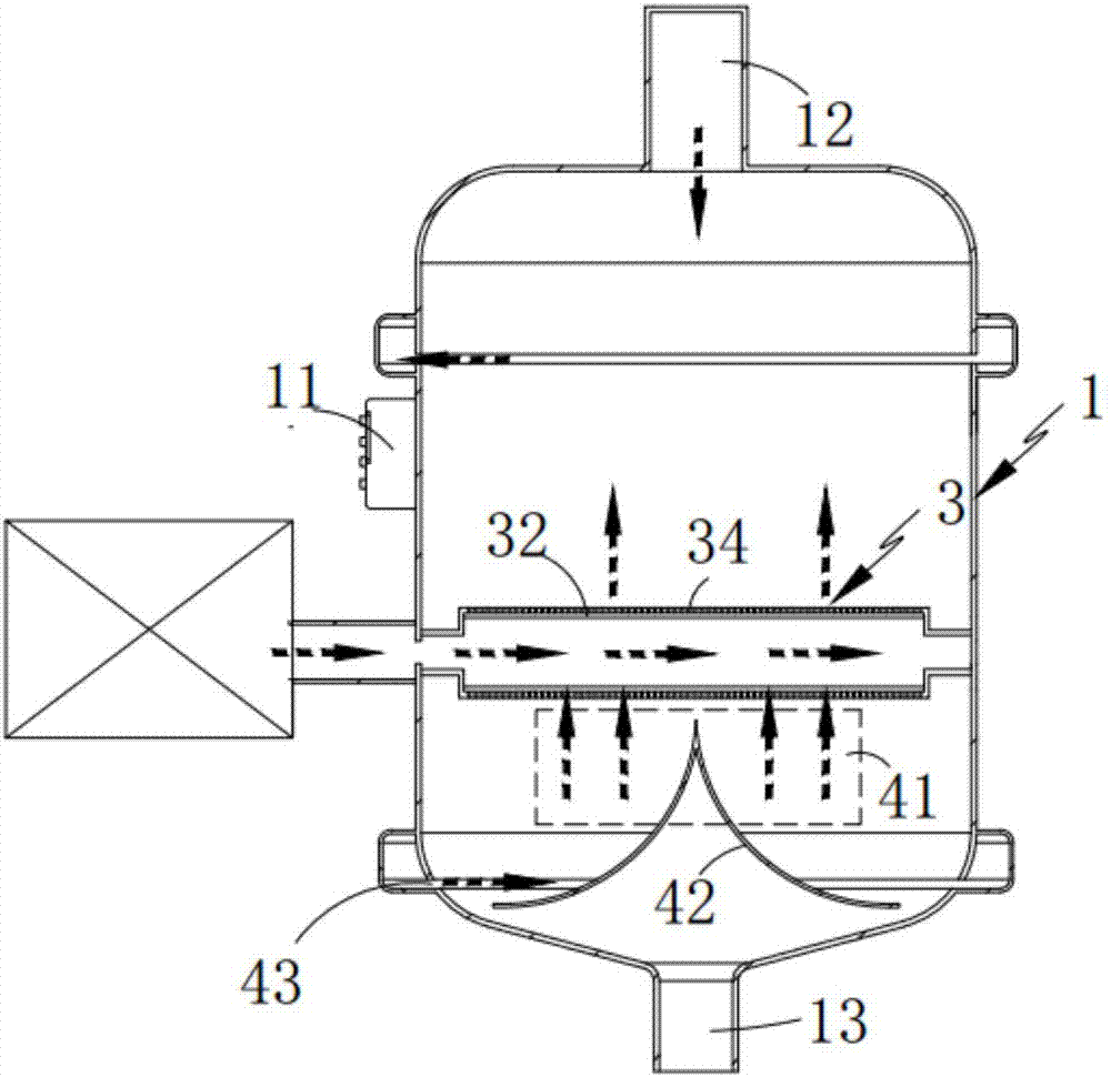
[0005] The object of the present invention is to address the deficiencies of the prior art, and provide a high-efficiency melting road paint mixing device, which sprays the air-powder mixture and the resin solution through the mixing assembly for rotating counter-spray mixing, and cooperates with the powder lifting assembly to remove the scattered powder. Secondary conveying and mixing of materials to solve the technical problems of uneven mixing and low utilization of powder in the prior art

Method used


Image

  • Efficient fused road coating mixing device
  • Efficient fused road coating mixing device
  • Efficient fused road coating mixing device

Examples


Embodiment 1

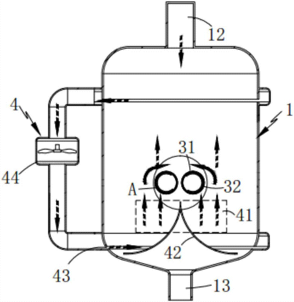
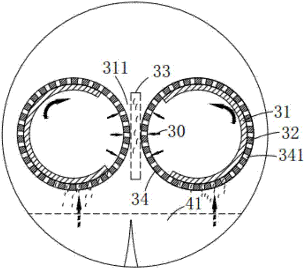
[0030] Such as figure 1 , 2 Shown in and 3, a kind of high-efficiency melting road paint mixing device, comprises melting chamber 1, also comprises:

[0031] Mixing assembly 3, the mixing assembly 3 is arranged in the melting chamber 1, the mixing assembly 3 is provided with an air injection part 34 communicating with its interior, and the gas-powder mixture inside the mixing assembly 3 is sprayed out through the air injection part 34 to form a directional Powder flow 30, the directional powder flow 30 is initially mixed with the powder during the liquid resin transmission process;

[0032] The powder blowing assembly 4, the mixed scattered powder is lifted by the powder blowing assembly 4 and then mixed with the initially mixed resin.

[0033] It should be noted that the mixing assembly 3 is a rotating roller 32 with a number of powder conveying holes 341 on the outer peripheral surface, and the gas-powder mixture in the interior is continuously sprayed out from the air inj...

Embodiment 2

[0041] Such as figure 1 , 2, 3 and 4, wherein the same or corresponding parts as in the second embodiment adopt the corresponding reference numerals with the second embodiment, for the sake of simplicity, only the difference between the second embodiment and the second embodiment is described below; the third embodiment and the implementation The difference of Example 2 is that the powder blowing port 43 is set intermittently.

[0042] It should be noted that, in this embodiment, the air flow for the flying treatment of the scattered filler falling on the blanking plate 42 is introduced from the upper part of the melting chamber 1 through the air flow generator 44, so that the inside of the mixing chamber 41 forms a lower and The upper gas flow direction, thereby reducing the falling speed of the scattered fillers, increasing the contact rate between the resin solution and the fillers, and at the same time ensuring a constant temperature in the melting chamber 1, thereby redu...


PUM


Abstract

The invention relates to an efficient fused road coating mixing device. The efficient fused road coating mixing device comprises a fusion bin, a mixing component and a power scattering assembly, wherein the mixing component is arranged in the fusion bin and comprises an air injection part formed in the mixing part, and an air-powder mixture located in the mixing component is sprayed out through the air injection part to generate a directional mixed powder flow and is primarily mixed with powder in a transmission process of liquid resin; and the scattered mixed powder is scattered by the powerscattering assembly to be secondarily mixed with the primarily mixed resin. The air-powder mixture is sprayed outwards by virtue of the mixing assembly so as to be rotatably counter-jetted and mixed with a resin solution, and the scattered powder is secondarily conveyed and mixed by virtue of the power scattering assembly, so that the technical problems in the prior art that the mixing is not uniform, and the utilization rate of the powder is low are solved.

Description

technical field [0001] The invention belongs to the field of municipal road equipment, in particular to a high-efficiency melting road paint mixing device. Background technique [0002] Line marking has become an important part of highway security construction. The discussion on line marking is no longer a discussion of whether the line marking is effective, but a discussion on how to provide the most effective marking system with the least investment; existing roads The markings will change color after long-term use, resulting in unclear road markings and easy to cause traffic accidents; the existing spray-type road marking machines need to fully stir and mix the paint in advance according to the specified ratio, and mix the mixed paint during construction. Put it into the road marking machine, and the mixed paint is easy to solidify, so it will solidify in the storage tank, pipeline, and valve, which greatly improves the maintenance rate of the equipment, and the leftover ...

Claims


Application Information

Patent Timeline
Patent Type & Authority Applications(China)
IPC IPC(8): B01F5/04B01F3/12B01F13/02B01F33/40
Inventor 蒋春生
Owner 长兴小浦凯荣机械加工厂
Learn More