Supercharge Your Innovation With Domain-Expert AI Agents!

Circular saw

A circular saw, disc-shaped technology, applied in the field of circular saws with surface roughness, can solve the problems that the suppression of cutting vibration cannot be eliminated, and the finished surface cannot be ensured.

Inactive Publication Date: 2018-01-02
KANEFUSA HAMONO KOUGIYOU KK
View PDF7 Cites 1 Cited by
  • Summary
  • Abstract
  • Description
  • Claims
  • Application Information

AI Technical Summary

Problems solved by technology

Through such a vibration prevention mechanism, the cutting vibration of the circular saw caused by the base metal itself can be suppressed, but the suppression of the cutting vibration caused by the cutting teeth itself cannot be eliminated.
Due to the cutting vibration caused by the cutting teeth themselves, even if the deflection angle of the circular saw is reduced to ensure a good finished surface, the desired finished surface cannot be ensured.

Method used


Image

  • Circular saw
  • Circular saw
  • Circular saw

Examples


Embodiment Construction

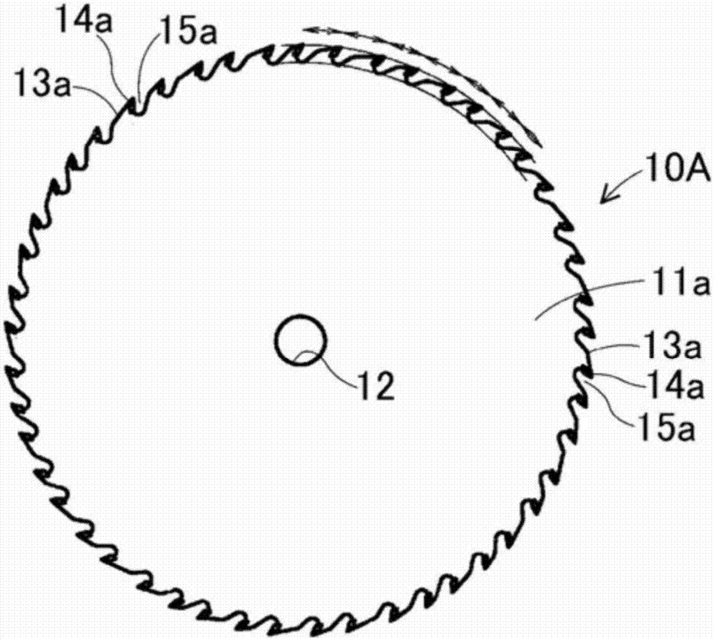
[0036] Embodiments of the present invention will be described below using the drawings. Figure 8 The circular saw 20 according to Example 1 is shown by an overall view. The base metal 21 constituting the circular saw 20 is a steel disk-shaped thin plate with an outer diameter of 305 mm×a tooth thickness of 2.8 mm, and a center hole 22 into which a rotating shaft of a machine to be processed is inserted is provided at the center thereof. The outer peripheral side of the base metal 21 forms approximately diamond-shaped blades 23 protruding in the radial direction at 72 positions in the circumferential direction, and each blade 23 is notched in an arc shape to form tooth chambers 24 recessed in the radial direction. On the front end side of each blade 23 in the rotation direction R, a mounting seat 25 for mounting a cutting tooth 28 is provided such that the cutout is substantially at a right angle.

[0037] Each blade 23 consists of three adjacent blades 23a, 23b, and 23c as a...


PUM


Abstract

This circular saw 10 has: cutting teeth 14 joined to a plurality of blade bodies 13 that protrude toward the outside in the radial direction at a plurality of locations on the outer circumference of adisc-shaped base metal 11; and gullets 15 which are recessed in the radial direction and formed between each of the plurality of blade bodies 13, wherein the chip clearance angle of the side surfacecutting blade of the cutting teeth 14 is within a range of less than + / -1 degree. The circular saw 10 is provided with a vibration prevention mechanism for preventing vibration of the base metal 11. The ratio of the difference between the maximum and minimum pitches of the plurality of cutting teeth 14 to the average pitch value is 40% to 100%. The ratio of the difference between the maximum and minimum values of the average depth of the neighboring gullets to the average depth of the gullets may be adjusted to 20% to 100%.

Description

technical field [0001] The present invention relates to a circular saw for cutting materials to be cut such as wood, wooden boards, resins, and non-ferrous metals such as aluminum, and more particularly to a circular saw capable of reducing the surface roughness of the finished surface of the cut material after cutting. Background technique [0002] Conventionally, in order to reduce the surface roughness of the finished surface of the workpiece cut by a circular saw and ensure a good finished surface, for example, as shown in Patent Document 1, cutting edges are cut on both side surfaces of cutting teeth that are bonded to a base metal. Set the bending point protruding to both sides so that the radial clearance angle from the bending point on the outer peripheral side (the radial clearance angle) is a negative value greater than -1° and less than 0°, so that the radial clearance angle from the bending point on the central side exceeds A positive value between 0° and 1°. he...

Claims


Application Information

Patent Timeline
Patent Type & Authority Applications(China)
IPC IPC(8): B23D61/02B23D47/00B27B33/08
CPCB23D61/021B23D61/04B23D61/025B23D61/02B23D47/00B27B33/08
Inventor 西尾悟竹山显
Owner KANEFUSA HAMONO KOUGIYOU KK
Features
  • R&D
  • Intellectual Property
  • Life Sciences
  • Materials
  • Tech Scout
  • Unparalleled Data Quality
  • Higher Quality Content
  • 60% Fewer Hallucinations
Learn More