Light intelligent energy-storage energy-releasing ankle prosthesis

An ankle joint, intelligent technology, applied in prosthesis, medical science, artificial legs, etc., can solve the problems of heavy prosthesis system, high price, wearer falling, etc., and achieve the effect of strong practicability, low cost, and easy walking.

Pending Publication Date: 2018-01-05
重庆德勒夫科技有限公司
View PDF0 Cites 5 Cited by
  • Summary
  • Abstract
  • Description
  • Claims
  • Application Information

AI Technical Summary

Problems solved by technology

Passive ankle joint prostheses use rubber, carbon fiber and other materials to make the foot plate, or introduce energy storage devices such as springs into the mechanism to make the whole foot have a certain degree of elasticity; however, the passive ankle joints currently on the market are generally cumbersome, and disabled people cannot walk flexibly after wearing them.
Passive ankle prosthesis has the advantages of simple mechanism, light weight, and low energy consumption. However, because the passive ankle prosthesis has no power source, there is a problem that the walking of amputee patients does not match the trajectory of normal limbs.
Active ankle prosthesis introduces active driving devices such

Method used


Image

  • Light intelligent energy-storage energy-releasing ankle prosthesis
  • Light intelligent energy-storage energy-releasing ankle prosthesis
  • Light intelligent energy-storage energy-releasing ankle prosthesis

Examples


Embodiment Construction

[0027] Below in conjunction with accompanying drawing and embodiment the present invention will be further described:

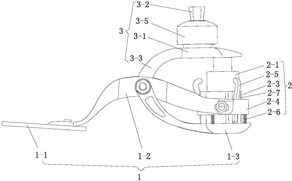
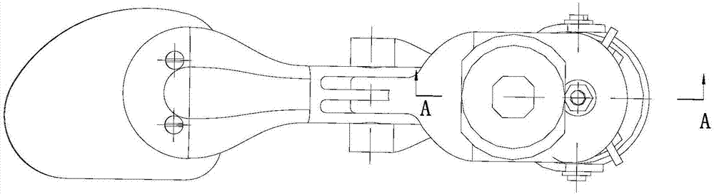
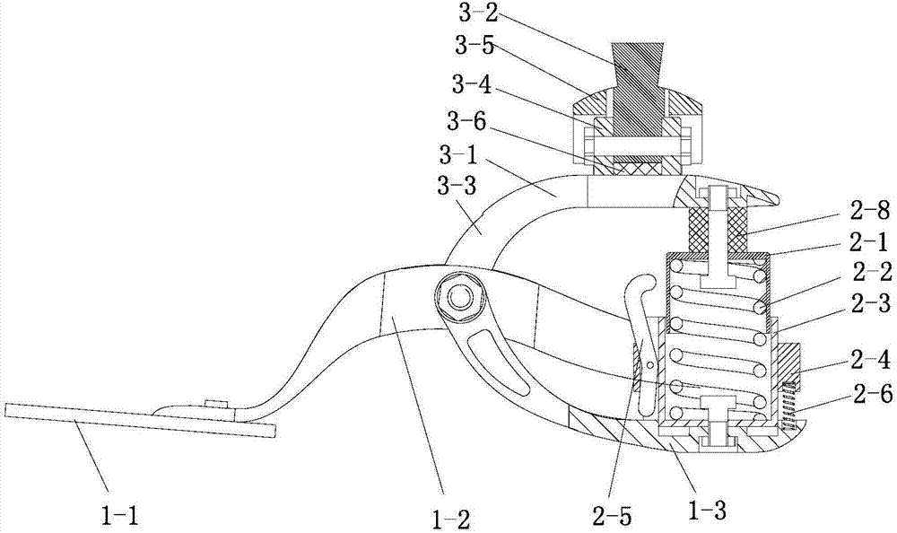
[0028] Such as Figure 1-Figure 6 A portable intelligent energy storage and energy release ankle joint prosthesis is shown, which consists of a bionic foot 1 , an ankle joint 2 and a tibial connection mechanism 3 . Bionic foot 1 is composed of sole 1-1, arched metatarsal bone 1-2, and heel 1-3. Ankle joint 2 is fixed on heel 1-3. One end of metatarsal bone 1-2 is fixed on sole 1-1, and the other end is U The ankle joint 2 is set in the U-shaped fork and connected together by bolts. The front end of the heel 1-3 extends obliquely upwards to form a U-shaped fork, and the middle part of the metatarsal bone 1-2 is sandwiched between the two forks. , and hinged together with bolts as horizontal axes. A weight-reducing hole is provided on the connecting arm of the heel 1-3.

[0029] Ankle joint 2 is mainly made up of spring cover 2-1, center spring 2-2, buffer i...


PUM


Abstract

The invention discloses a portable intelligent energy storage and energy release ankle joint prosthesis, which comprises a bionic foot, an ankle joint, and a tibial connection mechanism. Connected by bolts, the front end of the heel extends and hinges with the middle of the metatarsal bone; the ankle joint includes a spring cover, a central spring, a buffer inner ring, a buffer outer ring, multiple locking hooks, and multiple support springs, and the buffer inner ring is fixed on the heel, and the inner There is a center spring, the top of the center spring is covered with a spring cover, the buffer inner ring is provided with a plurality of locking hook grooves, the buffer outer ring is set outside the buffer inner ring, one end of the support spring is fixed on the heel, and the other end is fixed on the buffer The bottom of the outer ring; the tibial connection mechanism includes talus and tibial connection screws, the front end of the talus is hinged to the middle of the metatarsal bone, and the other end is connected to the spring cover. between the two lugs.

Description

technical field [0001] The invention relates to the technical field of human prosthesis, in particular to a portable intelligent energy storage and energy release ankle joint prosthesis. Background technique [0002] In today's society, due to traffic accidents, diseases and other reasons, the number of below-knee amputations is gradually increasing, and the most common ways for lower limb amputee to compensate for their walking ability defects are wheelchairs, crutches and artificial limbs. Wheelchairs occupy a large area and are limited to places that wheeled machines cannot reach, such as walking on stairs. The use of crutches takes up the functions of both hands and reduces the physical function of the wearer. Wearing prosthetics can achieve compensation for the missing functions of the human body, and has advantages in terms of decoration and walking comfort. [0003] At present, there are many types of ankle joint prostheses, classified according to the driving mode,...

Claims


Application Information

Patent Timeline
IPC IPC(8): A61F2/66A61F2/50
Inventor 叶延洪吕晓东杨其云胡龙刘海
Owner 重庆德勒夫科技有限公司
Why Eureka
Try Eureka