
Atomic spectral line detection device, system closed loop time measurement method and control method of modulation frequency and light intensity detection frequency

A detection device and atomic spectral line technology, which is applied in the field of atomic spectral line detection devices, can solve the problems of complex loop analysis, unanalyzable loop response time, inconvenient output of error signal acquisition and correction value of servo module, etc.

Pending Publication Date:
View PDF7 Cites 5 Cited by
  • Summary
  • Abstract
  • Description
  • Claims
  • Application Information

AI Technical Summary

Problems solved by technology

[0003] As we all know, in order to realize the precise detection of atomic spectral lines, it is necessary to cooperate with the peripheral servo circuit to realize resonance detection. However, in the actual servo control loop, the quantum system, etc. have nonlinear characteristics, and the loop analysis is very complicated, and the whole The loop response time of the system cannot be analyzed
Among them, the actual relaxation time of the physical system limits the loop response time of the entire system to a large extent. In addition, there are phase problems of each circuit module in the loop, which brings serious problems to the error signal acquisition of the servo module and the output of the corresponding correction amount. great inconvenience

Method used


Image

  • Atomic spectral line detection device, system closed loop time measurement method and control method of modulation frequency and light intensity detection frequency
  • Atomic spectral line detection device, system closed loop time measurement method and control method of modulation frequency and light intensity detection frequency
  • Atomic spectral line detection device, system closed loop time measurement method and control method of modulation frequency and light intensity detection frequency

Examples


Embodiment

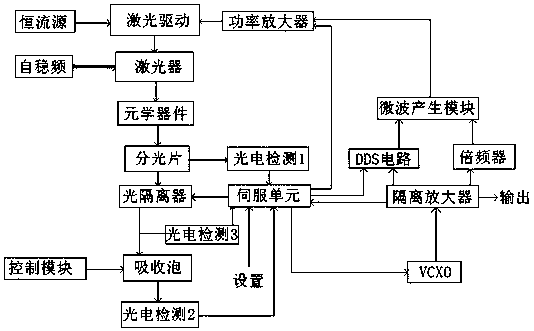
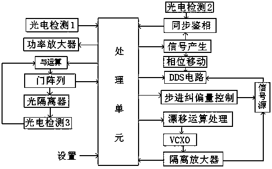
[0037] according to figure 2 As shown, the laser-based high-precision detection device for atomic spectral lines in the present invention includes a constant current source module, a power amplifier, a laser driver module, a laser, a self-stabilizing frequency module, a grating, a beam splitter, an optical isolator, a control module and The absorbing bubble also includes a servo unit, a first photoelectric detection module, a second photoelectric detection module, a third photoelectric detection module, a DDS module, a frequency multiplier, a microwave generation module, an isolation amplifier and a VCXO module.

[0038] Among them, the constant current source module provides a constant DC current for the laser driver module, the microwave signal output terminal of the power amplifier is connected to the signal input terminal of the laser driver module, and the laser driver module converts the microwave signal input by the power amplifier to the direct current input by the con...


PUM


Abstract

The invention relates to an atomic spectral line detection device, a system closed loop time measurement method and a control method of modulation frequency and light intensity detection frequency. The detection device comprises a constant current source module, a power amplifier, a laser driving module, a laser, a self-stabilization frequency module, a grating, a beam splitter, an optical isolator, a control module and an absorption bubble, and further comprises a servo unit, a first photoelectric detection module, a second photoelectric detection module, a third photoelectric detection module, a DDS module, a frequency multiplier, a microwave generation module, an isolation amplifier and a VCXO module. According to the detection device, after a loop is locked, each part only works in a small linear zone near the central frequency, and the closed loop process of the whole system from quantum frequency discrimination to servo deviation rectification of every time can be considered as constant. Based on this, the improved atomic spectral line high-precision detection device based on the laser, the system closed loop time measurement method and the control method of the modulation frequency and the light intensity detection frequency are provided.

Description

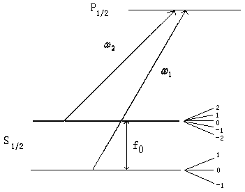
technical field [0001] The invention relates to the field of atomic spectral line detection, in particular to an atomic spectral line detection device, a system closed-loop time measurement method, and a control method for modulation frequency and light intensity detection frequency. Background technique [0002] Taking the rubidium atomic clock as an example, under the action of the magnetic field, the 87Rb in the absorbing bubble undergoes atomic splitting, forming such figure 1 The hyperfine triple-state energy level structure shown. in the picture is the energy level transition frequency of the two hyperfine structures in the ground state to the excited state, , which is 6.834GHz in 87Rb. In such an energy level structure, the laser current is modulated by microwaves, so that the laser spectrum produces two coherent modulation sidebands fM, when fM=1 / 2f0=3.417GHz, the ground state hyperfine energy level atoms in the absorbing bubble will be established A coherent t...

Claims


Application Information

Patent Timeline
Patent Type & Authority Applications(China)
IPC IPC(8): G01J3/28
Inventor 李星
Learn More