Optical switch device based on spiral optical fibers

An optical switch and optical fiber technology, which is applied in the field of optical switch devices based on helical optical fibers, can solve the problems of optical Kerr effect optical switches not being realized, and achieve the effects of improving stability and reliability and high integration

Inactive Publication Date: 2018-01-05
UNIV OF SHANGHAI FOR SCI & TECH
View PDF7 Cites 3 Cited by
  • Summary
  • Abstract
  • Description
  • Claims
  • Application Information

AI Technical Summary

Problems solved by technology

Therefore, optical switches based on the optical Kerr effect of polarization-maintaining fibers have not yet been realized

Method used


Image

  • Optical switch device based on spiral optical fibers
  • Optical switch device based on spiral optical fibers

Examples


Embodiment Construction

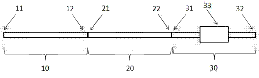
[0016] Such as figure 1 Shown is a schematic structural diagram of an optical switch device based on a helical fiber. The device is composed of a first helical fiber 10 , a second helical fiber 20 , and a fiber-coupled analyzer 30 connected in sequence. Wherein, the linearly polarized input end 11 of the first helical fiber 10 is used as the input end of the optical switch device, the elliptical polarization output end 12 of the first helical fiber 10 is connected with the elliptical polarization input end 21 of the second helical fiber 20, and the second helical fiber The linearly polarized output end 22 of 20 is connected to the input end 31 of the fiber-coupled polarizer 30, and the output end 32 of the fiber-coupled polarizer 330 is used as the final output end of the optical switch device.

[0017] The first spiral fiber 10 and the second spiral fiber 20 are two identical spiral fibers.

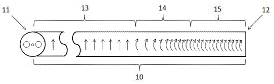
[0018] Such as figure 2 The schematic diagram of the spiral fiber shown in the ab...


PUM


Abstract

The invention relates to an optical switch device based on spiral optical fibers. The optical switch device is formed in the mode that the first spiral optical fiber, the second spiral optical fiber and an optical fiber coupling polarization analyzer is connected in sequence, wherein the first spiral optical fiber is completely same as the second spiral optical fiber. Each spiral optical fiber hasthree different refractive index intervals, wherein the first interval is a rotation-free interval, the second interval is a refractive index-variable interval, and the third interval is a uniform pitch interval. Linearly polarized light enters from the rotation-free interval of the first spiral optical fiber, and the elliptically polarized light exiting from the refractive index-variable interval of the first spiral optical fiber enters the refractive index-variable interval of the second spiral optical fiber, the linearly polarized light exiting from the rotation-free interval of the secondspiral optical fiber enters the optical fiber coupling polarization analyzer, and the output end of the optical fiber coupling polarization analyzer is taken as the final output end of the optical switch device. By means of the optical switch device, the disturbance of the outside environment can be overcome, such as the influence of temperature fluctuation and mechanical vibration on the all-optical switch performance. All parts of the optical switch are connected in a fiber splicing mode, so that the integration level of the system is high.

Description

technical field [0001] The invention relates to an optical fiber technology, in particular to an optical switch device based on a spiral optical fiber. Background technique [0002] All-optical switches have important applications in optical communication and information technology, such as computer optical interconnection, chip optical interconnection, communication switches, optical sensor networks, and so on. Optical communication is developing rapidly in the direction of high speed, integration, all-opticalization, and high stability. The all-optical switch does not require electro-optical conversion, and is realized by nonlinear optical methods, mainly using the optical Kerr effect. [0003] Polarization-maintaining fiber has the characteristics of polarization maintenance, can resist environmental interference, and has strong stability of transmitted signals. Therefore, it is of great significance to develop all-optical switches based on polarization-maintaining fibe...

Claims


Application Information

Patent Timeline
Patent Type & Authority Applications(China)
IPC IPC(8): G02B6/27G02B6/35
Inventor 郝强俞冰昊曾和平
Owner UNIV OF SHANGHAI FOR SCI & TECH
Why Eureka
Try Eureka