Laser circumferential seam welding fixture for multilayer thin-walled annular parts and method

A technology of annular parts and circumferential seams, which is applied in the field of laser circumferential seam welding fixtures for multi-layer thin-walled annular parts, can solve the problems of large welding deformation, increased deformation of parts, adhesion of parts and fixtures, etc., and achieves excellent thermal conductivity and heat dissipation. , Improve welding efficiency and prevent welding adhesion

Active Publication Date: 2018-01-09
AECC AVIATION POWER CO LTD
View PDF6 Cites 1 Cited by
  • Summary
  • Abstract
  • Description
  • Claims
  • Application Information

AI Technical Summary

Problems solved by technology

[0002] This method is a process method for laser circumferential seam welding of multi-layer thin-walled ring parts. At present, for multi-layer thin-walled ring parts, laser circumferential seam welding parts, traditional welding methods, for multi-layer (7 layers) δ = 0.25mm Circumferential seam welding of ring parts made of thin-walled GH605 is prone to ablation and collapse. Therefore, the welding method of laser circumferential seam welding is adopted, but when the welding method of laser circumferen

Method used


Image

  • Laser circumferential seam welding fixture for multilayer thin-walled annular parts and method
  • Laser circumferential seam welding fixture for multilayer thin-walled annular parts and method
  • Laser circumferential seam welding fixture for multilayer thin-walled annular parts and method

Examples


Embodiment 1

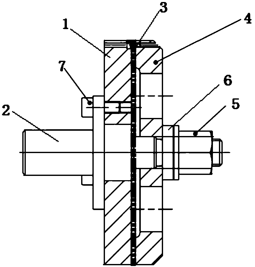
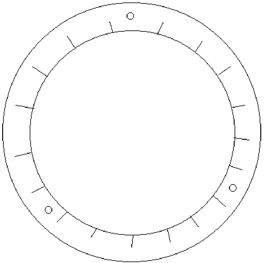
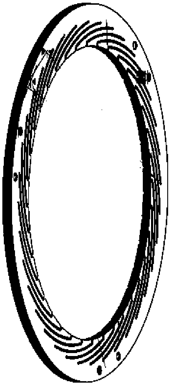
[0043] Such as Figure 1 to Figure 3 As shown, select a single-layer thin-walled ring with a thickness of δ=0.25mm, and the material is GH605; select a stepped mandrel 1, the axial diameter of the mandrel 1 is φ20mm, φ50mm, φ25mm, φ14mm, and the single-layer thin-walled ring The outer diameter of the part is 1 mm larger than the outer diameter of the positioning plate 1 and the pressure plate 4;

[0044] Clean the single-layer thin-walled ring, the positioning plate 1 and the pressure plate 4 with acetone, then install the positioning plate 1 into the φ25mm section of the mandrel 1, and fix it with the φ50mm section of the mandrel 2 through the screw 7, and then install Insert a plurality of single-layer thin-walled annular parts to be welded, and then press them through the pressure plate 4. When installing, ensure that the positioning holes on the positioning plate 1 and the pressure plate 4 are aligned to ensure that multiple single-layer thin-walled annular parts to be wel...


PUM

PropertyMeasurementUnit
Outer diameteraaaaaaaaaa

Abstract

The invention discloses a laser circumferential seam welding fixture for multilayer thin-walled annular parts and a method. To-be-welded multilayer thin-walled annular parts are clamped through a positioning disc and a pressing disc, and the external diameters of single layer thin-walled annular parts are greater than the external diameters of the positioning disc and the pressing disc, so that welding adhesion between the thin-walled annular parts and the positioning disc and the pressing disc is avoided; both the positioning disc and the pressing disc are made of red copper T2 material and are subjected to chrome-faced treatment; the excellent thermal conductivity and heat dissipation of the red copper are utilized so that welding deformation can be effectively prevented in the laser circumferential seam welding process of the multilayer thin-walled annular parts; non-adhesion during welding of a chromium coating and high-temperature materials are utilized so that welding adhesion between components and a fixture body can be effectively prevented, welding efficiency is greatly improved, and the qualified rate of product welding is ensured; in the welding process, the welding speed adopts the circumferential rotating speed being 0.95 r/min, the longitudinal feeding speed is 0.25 mm/r, and it can be ensured that a small section of welding seam is overlapped for each circumferential seam welding and the position of next circumferential seam welding is accurate.

Description

technical field [0001] The invention belongs to the technical field of welding technology, and in particular relates to a fixture and method for laser circumferential seam welding of multi-layer thin-walled annular parts. Background technique [0002] This method is a process method for laser circumferential seam welding of multi-layer thin-walled ring parts. At present, for multi-layer thin-walled ring parts, laser circumferential seam welding parts, traditional welding methods, for multi-layer (7 layers) δ = 0.25mm Circumferential seam welding of ring parts made of thin-walled GH605 is prone to ablation and collapse. Therefore, the welding method of laser circumferential seam welding is adopted, but when the welding method of laser circumferential seam welding is used, it is easy to cause adhesion between parts and fixtures. And the welding deformation is large, and the follow-up method of separation of fitters and thermal stabilization treatment with heat treatment fixtur...

Claims


Application Information

Patent Timeline
IPC IPC(8): B23K26/70B23K26/282B23K26/60B23K37/053
Inventor 司松社张翔邵志宏屈飞苏瑾吕震
Owner AECC AVIATION POWER CO LTD
Why Eureka
Try Eureka