Drill bit wear monitoring method

A drill bit and monitoring point technology, applied in the field of drill bit wear monitoring, can solve the problems of inability to detect small defects, low measurement accuracy, and inability to collect optical signals at the receiving end, so as to improve drilling quality, high measurement accuracy, The effect of improving accuracy

Inactive Publication Date: 2018-01-09
JILIN TEACHERS INST OF ENG & TECH
View PDF11 Cites 7 Cited by
  • Summary
  • Abstract
  • Description
  • Claims
  • Application Information

AI Technical Summary

Problems solved by technology

[0003] Therefore, the wear monitoring of the micro-drill is very important. However, in the prior art, a set of infrared light transceiver device connected with the computer control system is generally used to detect the wear and damage of the micro-drill blade, and the drill is placed in the optical path to form three Point a line, if the blade of the drill bit is intact, the light emitted by the transmitter will be blocked, and the receiver cannot collect the optical signal;

Method used


Image

  • Drill bit wear monitoring method
  • Drill bit wear monitoring method

Examples


Embodiment Construction

[0027] A specific embodiment of the present invention will be described in detail below in conjunction with the accompanying drawings, but it should be understood that the protection scope of the present invention is not limited by the specific embodiment.

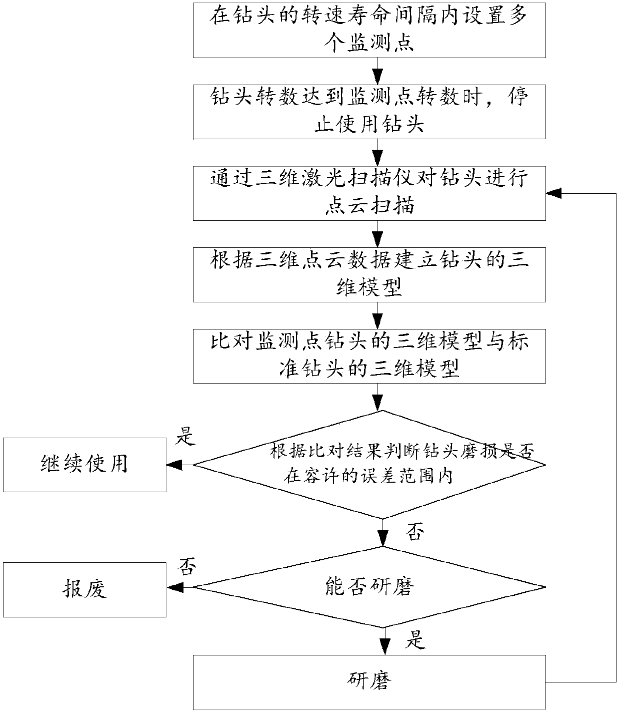
[0028] like figure 1 As shown, a drill bit wear monitoring method provided by an embodiment of the present invention includes the following steps:

[0029] S1. According to the service life of the drill bit provided by the supplier, set multiple monitoring points within the specified drill bit revolution life interval;

[0030] S2. Determine the number of revolutions of the drill bit by the number of revolutions of the motor that drives the drill bit. When the number of revolutions used by the drill bit reaches the number of revolutions at the monitoring point, stop using the drill bit;

[0031] S3. Scan the point cloud of the drill bit at the monitoring point through a three-dimensional laser scanner, and collect the thr...


PUM


Abstract

The present invention belongs to the drill bit detection technical field and discloses a drill bit wear monitoring method. The method includes the following steps that: S1, a plurality of monitoring points are set at the intervals of the life span of the number of times of rotation of a drill bit; S2, when the rotation of the drill bit achieves the number of times of rotation of the monitoring points, the use of the drill bit is stopped; S3, point-cloud scanning is performed on the drill bit at the monitoring points through using a three-dimensional laser scanner, so that the three-dimensionalcloud data of the drill bit can be acquired; S4, the three-dimensional model of the drill bit at the monitoring points is built through modeling software according to the three-dimensional point cloud data of the drill bit; S5, the three-dimensional model of the drill bit at the monitoring points is compared with the three-dimensional model of a standard drill bit; S6, whether the wear of the drill bit at the monitoring points is within an allowable error range is judged, when the wear of the drill bit exceeds the allowable error range, the drill bit is ground or scrapped; and S7, after the drill bit is ground, S3 to S6 are executed. The drill bit wear monitoring method has high measurement accuracy and can detect some small defects, thereby improving the quality of the hole drilling of the drill bit.

Description

technical field [0001] The invention relates to the technical field of drill bit detection, in particular to a method for monitoring drill bit wear. Background technique [0002] Due to the sharp increase in the demand for printed circuit boards, the consumption of PCB micro-drills used in the printed circuit board manufacturing industry has also continued to increase accordingly. With the development of the electronics industry, printed circuit boards have developed from the original single-layer board to multi-layer board. , flexible circuit boards, packaging substrates and HDI boards (High Density Interconnects high-density inline boards). The micro-connection holes on the PCB usually have a diameter of 0.05-0.30mm. These micro-connection holes are divided into three types: blind holes, buried holes and through holes. In the production process of PCB boards, hole processing is a very important process. The quality of drilling directly affects the final quality of PCB boa...

Claims


Application Information

Patent Timeline
IPC IPC(8): G01B11/00G01B11/24
Inventor 孙艳红田梅崔亚新
Owner JILIN TEACHERS INST OF ENG & TECH
Why Eureka
Try Eureka